- 11 -
3 HARDWARE INSTALLATION
Before removing or installing any of these devices including CPU, DIMMs, Add-On
Cards, Cables, please make sure to unplug the onboard power connector.
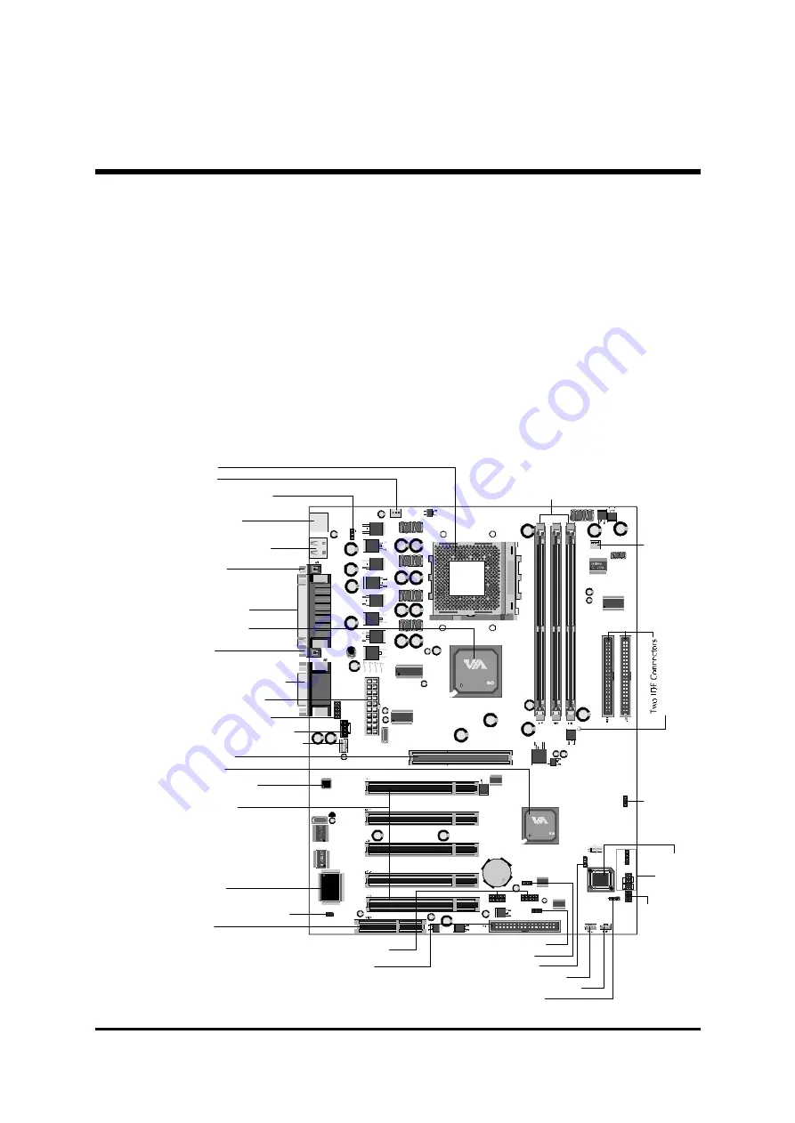
This section outlines how to install and configure your AK21 mainboard. Refer to the
following mainboard layout to help you identify various jumpers, connectors, slots, and
ports. Then follow these steps to guide you through a quick and correct installation of
your system.
3.1 Step-by-Step Installation
Accessories Of AK21
14
.3
2 4.5
AGP 1
USB 2
USB 3
JP 6
1
1
1
JP 7
1
USB1
PSKBM1
JP
1
CPUFAN1
JP 5
SO
C
KET
4
6
2
VT 8366
0038CD TAIWAN
1EE01921
C
VT 8233
003 6CG TAIWA N
12CON220 0
ICS 8102C
W230 -03 H
IT
87
12
F
-A
I T
E
A
UDI
O
1
1
1
CD2
CD1
J1
AT
X1
JP
4
SI
R1
RST
HDD
LE
D
GRN
LE
D
PW
R
SW
PAN
EL
1
SPE
AKE
R1
JP
3
LED1
CASFAN1
1
USB Power-On Setting -
JP6
PS2 Keyboard /
PS/2 Mouse Connectors
CPU FAN1
USB1/USB2 Connectors
Socket 462
Keybord & USB Power-On
Setting -
JP1
Serial Port
Connector (COM1)
Serial Port Connector
(COM2)
Parallel Connector
VIA KT266 Chipset
Line_out/Line_In/Microphone
MIDI/GAME Port Connectors
Primary CD-In Connector-
CD2
Secondary CD-In Connector-
CD1
CNR Slot
Floppy Connector
VIA VT8233
AGP 2x/4x Slot
Front-Panel Microphone/
Line-Out Header -
AUDIO1
ATX Power Connector
AC97 Audio CODEC
Five PCI Slots
Pr
og
ra
m
m
abl
e F
las
h
R
om
ITE I/O 8712
Case Open Alarm Header -
J1
Wake-On-Lan Connector -
WOL1
Clear CMOS Setting -
JP7
Wake-On-Modem Connector-
WOM1
BIOS Write Protection -
JP5
BIOS Voltage Setting -
JP4
Three DIMM Sockets
Extended USB
Headers -
USB2/U SB3
Fr
ont
P
one
l H
eade
r -
PA
N
EL
1
3V
SB
L
ED fo
r
SD
R
A
M
- -
LE
D
1
IR
He
ad
er
-
SI
R
1
FS
B
S
pe
ed C
onf
ig
ra
tion
Se
ttin
g -
JP
3
CA
S FA
N
1


