Shure Incorporated
37/37
1.
2.
3.
•
•
•
•
Shure Europe GmbH
Headquarters Europe, Middle East & Africa
Department: EMEA Approval
Jakob-Dieffenbacher-Str. 12
75031 Eppingen, Germany
Phone: +49-7262-92 49 0
Fax: +49-7262-92 49 11 4
Email: [email protected]
運用
に
際
しての
注意
この
機器
の
使用周波数帯
では、
電子
レンジ
等
の
産業
・
科学
・
医療用機器
のほか
工場
の
製造
ライン
等
で
使用
されている
移動体識別用
の
構内無線局
(
免許
を
要
する
無線局
)
及
び
特定小電力無線局
(
免許
を
要
しない
無線局
)
並
びにアマチュア
無線局
(
免許
を
要
する
無
線局
)が
運用
されています。
この
機器
を
使用
する
前
に、
近
くで
移動体識別用
の
構内無線局及
び
特定小電力無線局並
びにアマ チュア
無線局
が
運用
さ
れていないことを
確認
して
下
さい。
万一
、この
機器
から
移動体識別用
の
構内無線局
に
対
して
有害
な
電波干渉
の
事例
が
発生
した
場合
には、
速
やかに
使用周波
数
を
変更
するか
又
は
電波
の
発射
を
停止
した
上
、
下記連絡先
にご
連絡頂
き、
混 信回避
のための
処置等
(
例
えば、パーティ
ションの
設置
など)についてご
相談
して
下
さい。
その
他
、この
機器
から
移動体識別用
の
特定小電力無線局
あるいはアマチュア
無線局
に
対
して
有害
な
電波干渉
の
事例
が
発生
した
場合
など
何
かお
困
りのことが
起
きたときは、
保証書
に
記載
の
販売代 理店
または
購入店
へお
問
い
合
わせください。
代
理店
および
販売店情報
は
Shure
日本語
ウェブサイト
でもご
覧
いただけます。
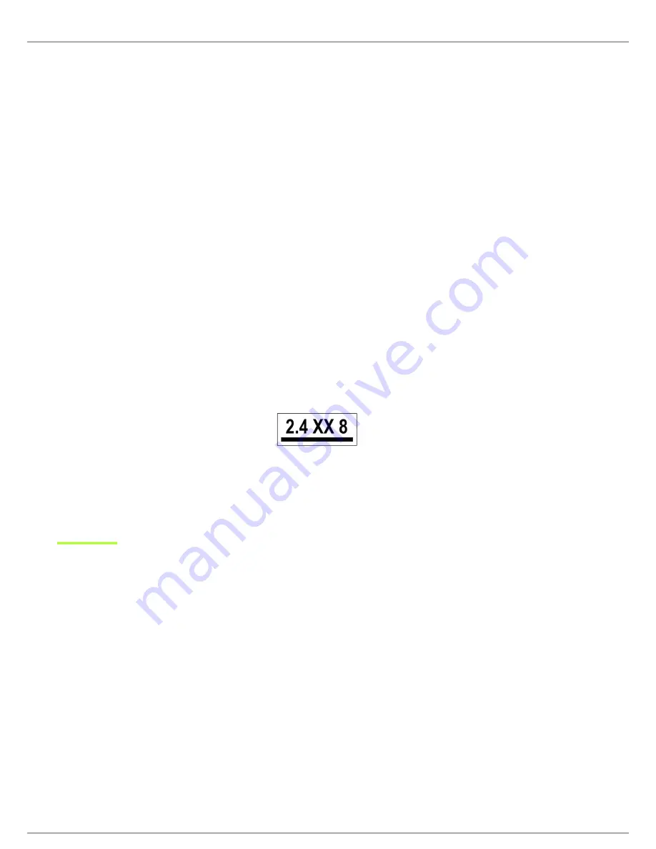
現品表示記号
について
現品表示記号
は、
以下
のことを
表
しています。 この
無線機器
は
2.4GHz
帯
の
電波
を
使用
し、
変調方式
は「その
他
」の
方式
、
想定与
干渉距離
は
80m
です。
2,400MHz
~
2,483.5MHz
の
全帯域
を
使用
し、
移動体識別装置
の
帯域
を
回避
することはできません。
Information to the user
This equipment has been tested and found to comply with the limits for a Class B digital device, pursuant to Part 15 of the FCC
Rules. These limits are designed to provide reasonable protection against harmful interference in a residential installation. This
equipment generates uses and can radiate radio frequency energy and, if not installed and used in accordance with the in
structions, may cause harmful interference to radio communications. However, there is no guarantee that interference will not
occur in a particular installation. If this equipment does cause harmful interference to radio or television reception, which can be
determined by turning the equipment off and on, the user is encouraged to try to correct the interference by one or more of the
following measures:
Reorient or relocate the receiving antenna.
Increase the separation between the equipment and the receiver.
Connect the equipment to an outlet on a circuit different from that to which the receiver is connected.
Consult the dealer or an experienced radio/TV technician for help.