background image

Shure Incorporated

22/37

1.

2.

3.

Position antennas so there is nothing obstructing the line of sight to the transmitter, including the audience.

Keep antennas away from metal objects and any other antennas.

Use only low-loss reverse SMA cable to avoid poor RF signal.

Consult cable's specifications and calculate signal loss for desired cable run.

Use one continuous length of cable from the antenna to the receiver to increase signal reliability.

Always perform a walk­around test to verify coverage before using a wireless system during a speech or performance. Ex­

periment with antenna placement to find the optimum location. If necessary, mark any trouble spots and ask presenters or 

performers to avoid those areas.

Multiple Receiver Systems

To run more than two receivers at the same time, the GLX-D Frequency Manager is recommended to improve RF reliability.

However, you can run multiple receivers without the frequency manager. Select the group by determining the total number of 

receivers in your system (channel count). All receivers in the system must be set to the same group.
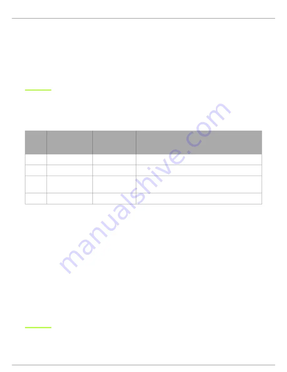
Group

Channel Count 

(Number of Re-

ceivers)

Number of Backup 

Frequencies Per 

Channel

Notes

1

Up to 4

3

Initial factory setting.

2

Up to 5*

3

Best 

multi-channel

 group if you experience interference.

3

Up to 8*

0

Only use Group 3 in controlled Wi-Fi environments because 

there are no backup frequencies to avoid interference.

4

1

27

Best 

single-channel

 group if you experience interference.

*Environmentally dependent, 4 systems typical

See "Tips to Improve Wireless System Performance" section for additional information. For information about receiver groups 

when connected to the GLX-D Frequency Manager, see the UA846 user guide.

Setting Up Receivers and Transmitters

Note:

 Before beginning, turn off all receivers and transmitters. Turn on and set up each receiver/transmitter pair individually to prevent cross-linking.

Turn on the first receiver.

Press and hold the group button to select a group (if necessary) or if the group is already set, press the channel button 

to scan for the best available channel.

Turn on the first transmitter. The rf LED turns solid blue when a link is established.

Repeat steps 1-3 for each additional receiver and transmitter. Remember to set each receiver to the same group.

See GLX-D Frequency Manager guide for setting up receivers and transmitters when connected to the frequency manager.

Note:

 Dashes appearing on the group and channel display during a channel scan indicate that frequencies are not available in the selected group. Choose a 

group that supports more receivers and repeat set-up steps.

Summary of Contents for GLXD1

Page 1: ...GLXD4R Half Rack Wireless Receiver Complete user guide for the GLXD4R wireless system Includes installation instructions best practices specifications and troubleshooting Version 4 1 2020 K...

Page 2: ...Transmitter 17 Charging Times and Transmitter Runtimes 17 Important Tips for Care and Storage of Shure Recharge able Batteries 18 2 4 GHz Spectrum Overview 18 Overcoming the Challenges of 2 4 GHz 18 C...

Page 3: ...Shure Incorporated 3 37 Pin Assignments 32 GLXD2 33 Receiver Output Connectors 36 Certifications 36 Information to the user 37...

Page 4: ...LY USE attachments accessories specified by the manufacturer USE only with a cart stand tripod bracket or table specified by the manufacturer or sold with the apparatus When a cart is used use caution...

Page 5: ...t may cause burns or catch fire Do not charge or use battery packs with other than specified Shure products Dispose of battery packs properly Check with local vendor for proper disposal of used batter...

Page 6: ...Adjustable transmitter gain to optimize audio signal Automatically moves away from interference without audio interruption RF back channel for remote control of transmitter functions Automatic transmi...

Page 7: ...r automatically link to form an audio channel the first time they are powered on and never have to be linked again Step Connect power supply to the receiver and plug cord into an AC power source Conne...

Page 8: ...8 37 Note The transmitter and receiver will remain linked for future usage At power up the blue rf LED and transmitter LED will illuminate skipping the linking step Step Check the audio and adjust the...

Page 9: ...Shure Incorporated 9 37 Receiver Controls and Connectors...

Page 10: ...nd hold for two seconds to enable manual group edit Data Sync LED ON Data sync is on receiver connected to GLX D Frequency Manager Flashing Searching for frequencies OFF Data sync is off receiver not...

Page 11: ...y Charges transmitter battery if receiver is plugged in to power outlet Power Button Powers the unit on and off Antenna Two antennas per receiver Antennas pick up the signal from the transmitter Power...

Page 12: ...attery Audio Meter Indicates audio signal level and peaks Gain Displays transmitter gain settings dB OL Indicator Indicates audio overload reduce gain Transmitter Locked Displayed when linked transmit...

Page 13: ...k with receiver Press momentarily to activate Remote ID function Battery Compartment Holds 1 Shure rechargeable battery Microphone Cartridge GLXD 2 transmitter models are available with the following...

Page 14: ...er Flashing battery error replace battery Wearing the Bodypack Transmitter Clip the transmitter to a belt or slide a guitar strap through the transmitter clip as shown For best results the belt should...

Page 15: ...ry maximizes runtimes with zero memory effects eliminating the need to discharge batteries prior to charging When not in use recommended battery storage temperature is 10 C 50 F to 25 C 77 F Note The...

Page 16: ...cable into the charging port on the transmitter Plug the cable into a standard USB port LED Status During Charging The following LED states indicate battery status when the transmitter is connected to...

Page 17: ...Unscrew and remove the battery cover Place the battery into the transmitter Replace and tighten the battery cover Charging Times and Transmitter Runtimes Use the following table to determine approxim...

Page 18: ...that Wi Fi traffic can be unpredictable GLX D meets these challenges in the following ways Prioritizes and transmits on the best three frequencies per channel choosing from a pool of six frequencies a...

Page 19: ...smissions across manufacturers all 2 4 GHz wireless currently on the market use different variations of wireless transmission These differences make it more difficult to mix and match 2 4 GHz systems...

Page 20: ...Shure Incorporated 20 37...

Page 21: ...ters or microphone cartridges audible noise is possible Move transmitter and receiver away from metal or other dense materials During sound check mark trouble spots and ask performers to avoid those a...

Page 22: ...ing 2 Up to 5 3 Best multi channel group if you experience interference 3 Up to 8 0 Only use Group 3 in controlled Wi Fi environments because there are no backup frequencies to avoid interference 4 1...

Page 23: ...n the transmitter is active Important Do not turn on and operate both linked transmitters at any time Turn off both transmitters before beginning Press the group button to select a group The receiver...

Page 24: ...NK button while turning on the transmitter Continue to hold the link button until the lock icon appears on the receiver LCD Repeat sequence to unlock Optionally the transmitter power switch can be rem...

Page 25: ...y flashes Press the group button to scroll through the available groups The receiver will automatically save the selected group Selecting a Channel Press and hold the channel button for 2 seconds unti...

Page 26: ...ure com update utility Connect to the Computer Connect the device to your computer using the USB to Micro USB cable supplied with your GLX D system Rack Mounting Instructions Use the supplied mounting...

Page 27: ...Shure Incorporated 27 37...

Page 28: ...ed see Adjusting Gain Verify that the receiver is connected to mixer amplifier Receiver RF LED off Turn on transmitter Make sure the batteries are installed correctly Link transmitter and receiver see...

Page 29: ...pears on receiv er LCD Reduce transmitter gain see Gain Adjustment Transmitter and receiver link unsuccessful Transmitter and receiver LEDs flash to indicate that linking start ed but the link fails U...

Page 30: ...s behind antennas in the null to minimize interfer ence Place receivers or directional antennas closer to transmitters Resetting Components Use the reset function if it is necessary to restore the tra...

Page 31: ...8 dBm typical Total Harmonic Distortion 0 2 typical RF Output Power 10 mW E I R P max Operating Temperature Range 18 C 0 F to 57 C 135 F Storage Temperature Range 29 C 20 F to 74 C 165 F Polarity Posi...

Page 32: ...ng Cast Metal Black Powdercoat Input Impedance 900 k RF Output Power 10 mW E I R P max Transmitter Input Connector 4 Pin male mini connector TA4M Configuration Unbalanced Maximum Input Level 1 kHz at...

Page 33: ...3 37 GLXD2 Dimensions Model A B C SM58 51 mm 2 0 in 252 mm 9 9 in 37 mm 1 5 in BETA 58 51 mm 2 0 in 252 mm 9 9 in 37 mm 1 5 in SM86 49 mm 1 9 in 252 mm 9 9 in 37 mm 1 5 in BETA 87A 51 mm 2 0 in 252 mm...

Page 34: ...nts 3 7 V Rechargeable Li Ion RF Output Power 10 mW E I R P max Maximum Input Level SM58 146 dB SPL BETA 58 147 dB SPL SM86 143 dB SPL BETA 87A 147 dB SPL Dimensions 42 x 197 x 163 mm 1 7 x 7 8 x 6 4...

Page 35: ...tput 100 6 35 mm 1 4 output 100 50 Unbalanced Full Scale Output 1 4 6 35 mm 12 dBV XLR LINE setting 18 dBV MIC setting 12 dBV Mic Line Switch 30 dB pad Pin Assignments XLR Output 1 ground 2 hot 3 cold...

Page 36: ...is device may not cause interference and 2 this device must accept any interference including interfer ence that may cause undesired operation of the device Le pr sent appareil est conforme aux CNR d...

Page 37: ...enerates uses and can radiate radio frequency energy and if not installed and used in accordance with the in structions may cause harmful interference to radio communications However there is no guara...

Reviews: