background image

Manual: ShowNET - Network Interface

Manual: ShowNET - Network Interface

page 14 / 63

page 15 / 63

(2a)  Professional Mode - Setup-and-Store - Global Settings via Admin Tool
 

Since firmware 202002xx it is possible to adjust e.g. a projection zone, a safety zone, color 

balancing, geometric corrections, etc. with the Admin Tool or directly via DMX and store 

these settings to the ShowNET mainboard.

This procedure describes the adjustment of the global settings wih the 

Admin Tool

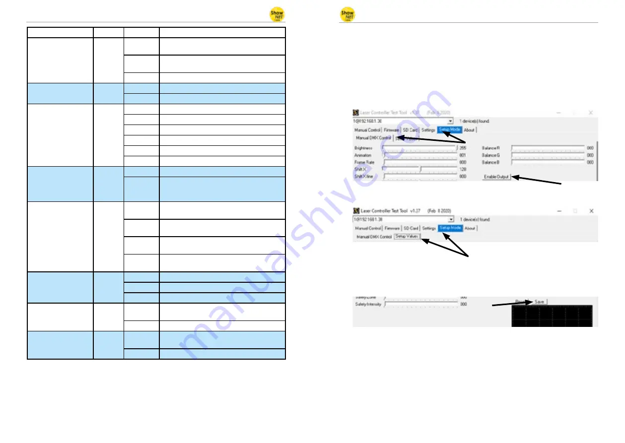
To do so, enable the laser output first. Switch to the tab ‚Setup Mode‘ -> ‚Manual DMX 

Control‘ and then click on  ‚Enable Output‘. The laser output will flash every few seconds 

to indicate that the test mode of the admin tool is active.

Select the tab ‚Setup Mode‘ -> ‚Setup Values‘ as shown in the picture below:

Adjust the settings (besides the laser output, the little window in the bottom right of 

the ‚Setup Value‘ tab will display the changes, too) and then store them to the ShowNET 

mainboard with a click on ‚Save‘. The laser output will flash three times to confirm that the 

changes have been saved.

The settings will be saved until either the ‚dmxconf‘ data gets deleted from the SD Card, 

the settings will be resetted with a click on ‚Reset‘ on the Setup Values tab, or new settings 

will be saved with a click on ‚Save‘ on the ‚Setup Values‘ tab.

It is also possible to save, change and reset settings directly via DMX. See the next chapter 

for details on how to do this. 

As the settings via DMX are the same as the settings in the ‚Setup Values‘ tab, please refer 

to the following DMX chart for detailled explanation of the specific global adjustments.

Channel

Mode

Value

Function

12 Color effects

extended

DJ

0 - 127

Smooth color fade effect to the re-color effect

Value of channel 11 must be >15!

128 - 192

Blocking color effect to the re-color effect

Value of channel 11 must be >15!

193 - 255

Automatic change of color fade effects

13 Strobe

DJ

0 - 15

None

16 - 255

Increasing strobe effect

14 Operation mode

DJ

0 - 19

DMX

20 - 83

Automatic position X & Y-axis

84 - 147

Automatic position X-axis

148 - 211

Automatic position Y-axis

212 - 233

Demonstration mode

234 - 255

Sound-to-light

15 Scan speed

DJ

0 - 31

Default

32 - 255

Increasing scan speed (from 5 kpps to 30 kpps)

ATTENTION

: If you‘re unsure about the maxi-

mum scan speed, stay with the default setting! 

16 Safety zone size

DJ

0 - 63

Size of horizontal safety zone

Safety zone is the bottom side

64 - 127

Size of horizontal safety zone

Safety zone is the upper side

128 - 191

Size of vertical safety zone

Safety zone is the left side

192 - 255

Size of the vertical safety zone

Safety zone is the right side

17 Safety zone intensity

DJ

0

No reduction

1 - 128

Decrease brightness up to half brightness

129 - 255

Decrease brightness up to blackout

18 Blanking

DJ

0 - 192

Manual select how much of the laser pattern 

shall be blanked

193 - 255

Automatic blanking (increasing speed)

19 Blankshift

DJ

0 - 192

Manual select the pattern part the blanking of 

channel 18 shall be applied to

193 - 255

Automatic blank shift (increasing speed)

Summary of Contents for Laserworld OEM

Page 1: ...face Please read this manual carefully prior to product operation Bitte lesen Sie diese Bedienungsanleitung vor Inbetriebnahme des Produkts Avant d utiliser cet appareil pour la première fois nous vous recommandons de lire cette notice d utilisation 02 2020 English Deutsch Français ...

Page 2: ...difications con cernant leurs produits et ainsi de répondre au développement technique Ces modifications ne seront pas nécessairement annoncées en tout cas spécifique Ce mode d emploi et les in formations contenues dedans ont été établis avec le soin minutieux qui s impose dans ce cas Laserworld Switzerland AG ne pourra pas être tenue responsable pour d éventuelles erreurs d impression ou dommages...

Page 3: ...e sure to use correct voltage see in formation in this manual 2 Installation has to be done by technical experienced and qualified persons ac cording to safety regulations of the res pective country 3 If the network interface has been expo sed to great temperature changes do not switch it on immediately Conden sation water may damage the network interface 4 Avoid exposure to high temperatures or h...

Page 4: ...tput could occur To change DIP switch settings always power off device then change DIP settings and finally power up your device again 5 Operation Operation Modes Firmware version 202002xx Admin tool v1 37 1 Download admin tool For testing the show laser system and for other purposes like uploading ILDA files to the SD card without the need for an external card reader download the admin tool here ...

Page 5: ...own in the picture below Select the folder with the ILDA files on the local hard drive by clicking on the button with the three points on it IMPORTANT Custom laser files have to be stored in ild format and must be named with a number from 001 ild to 255 ild Each number represents a DMX value on the respective fader To upload ild files greater than 6 MB please use an external card reader Otherwise ...

Page 6: ... Mode Sound to Light available as an option MASTER unit switch 1 2 3 4 5 6 7 8 9 10 On 1 Off 0 0 0 0 0 1 0 1 0 1 0 SLAVE units switch 1 2 3 4 5 6 7 8 9 10 On 1 Off 0 0 0 0 0 0 1 1 1 0 0 To have the same effects show on all connected units it is required to have the same pattern sets on all SD cards inside the units g Master Slave Mode Demo Mode MASTER Demo Mode switch 1 2 3 4 5 6 7 8 9 10 On 1 Off...

Page 7: ...annel Mode Value Function 1 Intensity DJ 0 Laser off 1 255 Increase intensity full intensity 255 2 Pattern selection DJ 0 Blackout 000 ild must not exist 1 255 Display patterns from SD card 1 001 ild 2 002 ild and so on If no pattern is assigned to a number blackout 3 Pattern speed Framerate DJ 0 15 Standard speed 50 fps 16 255 Increasing speed from 0 fps to 100 fps 4 Size DJ 0 127 Decreasing size...

Page 8: ...on how to do this As the settings via DMX are the same as the settings in the Setup Values tab please refer to the following DMX chart for detailled explanation of the specific global adjustments Channel Mode Value Function 12 Color effects extended DJ 0 127 Smooth color fade effect to the re color effect Value of channel 11 must be 15 128 192 Blocking color effect to the re color effect Value of ...

Page 9: ...4 95 Channel Mode Value Function 1 Intensity Prof 0 Laser off 1 255 Increase intensity full intensity 255 2 Pattern Selection Prof 0 Blackout 000 ild must not exist 1 255 Display patterns from SD card 1 001 ild 2 002 ild and so on If no pattern is assigned to a number blackout 3 Pattern Speed Framerate Prof 128 Standard speed 50 fps 0 127 Increasing speed from 0 fps tp 50 fps 129 255 Increasing sp...

Page 10: ...up Color Balancing Red Prof 0 255 From max intensity 0 to no intensity 255 22 Color Balancing Green for white balance Prof 0 255 From max intensity 0 to no intensity 255 Master to channel 15 22 Setup Color Balancing Green Prof 0 255 From max intensity 0 to no intensity 255 23 Color Balancing Blue for white balance Prof 0 255 From max intensity 0 to no intensity 255 Master to channel 16 23 Setup Co...

Page 11: ...e available in the network For example this could be a cheap 100MBit network router with integrated DHCP server This option does not work if there is no device in the same network that can distribute and manage network addresses as DHCP In this case try AutoIP as connection method e g if the interface is directly connected to the computer b AutoIP switch 1 2 3 4 5 6 7 8 9 10 On 1 Off 0 0 0 0 0 0 1...

Page 12: ...011 IP sender 192 168 2 82 sends to 192 168 2 62 1011 IP sender 192 168 2 83 sends to 192 168 2 63 0111 IP sender 192 168 2 84 sends to 192 168 2 64 1111 IP sender 192 168 2 85 sends to 192 168 2 65 sender 0 receiver 1 0 1 1 0 0 Example Sender IP address setting switch 1 2 3 4 5 6 7 8 9 10 On 1 Off 0 0 0 0 1 0 0 1 1 0 0 This assigns IP address 192 168 2 78 to the Sender The corresponding receiver ...

Page 13: ...gestellt sein dass das Netz werk Interface mit der richtigen Span nung betrieben wird siehe Angaben in dieser Bedienungsanleitung 2 Die Installation darf nur von technisch versiertem Fachpersonal gemäss der im jeweiligen Land geltenden Sicherheits bestimmungen installiert werden 3 Wenn das Gerät großen Temperatur schwankungen ausgesetzt war schalten Sie es nicht unmittelbar danach an Kon denswasse...

Page 14: ... Lasersystems und für andere Zwecke wie z B speichern von ILDA Datei en auf der eingesteckten SD Karte kann das Admin Tool hier heruntergeladen werden https www laserworld com shownet_mainboard Öffnen Sie ShowNET Admin_Tool exe wenn diese Anleitung auf das Admin Tool Bezug nimmt WICHTIG Es ist nicht möglich mit dem Admin Tool auf den Laser zuzugreifen wenn gleichzeitig eine Lasersoftware auf den S...

Page 15: ...ld zu sehen Wählen Sie den Ordner mit den ILDA Dateien auf Ihrer lokalen Festplatte aus indem Sie auf die Schaltfläche mit den drei Punkten klicken WICHTIG Benutzerdefinierte Lasergrafiken müssen im ild Format gespeichert und mit einer Nummer von 000 ild bis 255 ild versehen sein Jede Zahl repräsentiert einen DMX Wert von 0 bis 255 Um ild Dateien größer als 6 MB hochzuladen verwenden Sie bitte ein...

Page 16: ...ie auf der SD Karte gespeicherten ild Dateien zum Klang von Umgebungsgeräuschen abgespielt und animiert f Master Slave im Musikmodus MASTER Projektor Schalter 1 2 3 4 5 6 7 8 9 10 An 1 Aus 0 0 0 0 0 1 0 1 0 1 0 SLAVE Projektoren Schalter 1 2 3 4 5 6 7 8 9 10 An 1 Aus 0 0 0 0 0 0 1 1 1 0 0 Damit auf allen Projektoren dieselben Effekte dargestellt werden müssen auf allen in tegrierten SD Karten dies...

Page 17: ... Hinweis Betreiben Sie die Scanner Galvos nur mit der angegebenen Geschwindig keit bezogen auf den Winkel Eine zu schnelle Wiederholfrequenz führt zu Schäden am Scan System 1 DJ Modus Um eine Laserausgabe zu erhalten stellen Sie für DMX Kanal 1 einen Wert größer als 0 ein z B ein Wert zwischen 128 und 159 für den Automatikmodus Kanal Modus Wert Funktion 1 Helligkeit DJ 0 Laser aus 1 255 Helligkeit...

Page 18: ...nuelle Auswahl auf welche Teile des Musters Kanal 18 Blanking angewendet werden soll 193 255 Automatische Auswahl Geschwindigkeit wird erhöht 2a Professional Modus Setup und Speichern Globale Einstellungen via Admin Tool Seit der Firmware 202002xx ist es möglich einen Projektionsbereich eine Safety Zone die Farbbalance geometrische Korrekturen etc mit dem Admin Tool oder direkt über DMX einzustell...

Page 19: ...rofessional Modus DMX Tabelle Orangene Zeilen sind auswählbar im Setup Modus Kanal 24 134 135 und Kanal 25 94 95 Kanal Wert Funktion 1 Helligkeit Prof 0 Laser aus 1 255 Helligkeit erhöhen volle Helligkeit 255 2 Musterauswahl Prof 0 Blackout 000 ild darf nicht existieren 1 255 Gespeicherte Muster darstellen 1 001 ild 2 002 ild und so weiter Falls eine Nummer nicht exisitert Blackout 3 Bildrate der ...

Page 20: ...Save Modus in Kombination mit Kanal 25 211 212 Reset Modus in Kombination mit Kanal 25 0 133 Lasershow Modus 136 203 206 210 213 255 Kanal Wert Funktion 25 Setup Modusauswahl Prof 94 95 Setup Modus in Kombination mit Kanal 24 168 169 Save Modus in Kombinationmit Kanal 24 32 33 Reset Modus in Kombination mit Kanal 24 0 31 Lasershow Modus 34 93 96 167 170 255 26 Setup Geo Korrektur Trapezförmig X Ac...

Page 21: ...es Netzwerkbetriebs Die IP Adresse besteht aus 4 Zahlenblöcken die durch einen Punkt abgetrennt sind Die ersten beiden Zahlenblöcke sind immer 192 168 und können nicht geändert werden Die hinteren beiden Zahlenblöcke adr1 and adr2 können mit den Dip Schaltern modifiziert werden Die sich ergebende IP Adresse sollte dieser in etwa gleichen 192 168 adr1 adr2 Schalter 1 2 3 4 5 6 7 8 9 10 An 1 Aus 0 0...

Page 22: ...se 192 168 2 78 zu Das dazugehörige Empfänger Interface benötigt daher folgende Adresseinstellung Schalter 1 2 3 4 5 6 7 8 9 10 An 1 Aus 0 0 0 0 1 1 0 1 1 0 0 Diese Einstellung weist dem Empfänger die IP Adresse 192 168 2 58 zu Der einzige Unterschied zwischen Sender und Empfänger ist die Schaltereinstellung des Schalters mit der Nummer 5 die beim Sender 0 beim Empfänger 1 ist Abschließende Erklär...

Page 23: ...ous assurer de brancher l appareil sur une prise électrique déliv rant la tension de fonctionnement cor recte voire les instructions dans ce mode d emploi 2 Cet interface réseau ne doit être installé que par des ouvriers qualifiés en tech nique selon les normes et règlementa tions de sécurité des pays respectifs 3 Si l appareil a été exposé à de gran des fluctuations de température ne l allumez pa...

Page 24: ...re 202002xx Admin tool v1 37 1 Télécharger le logiciel Admin tool Pour tester le projecteur laser ainsi que pour d autres applications telles que le téléchar gement de fichiers ILDA sur la carte SD veuillez télécharger le logiciel d administration Admin tool ici https www laserworld com shownet_mainboard Lancez le fichier ShowNET Admin_Tool exe chaque fois que ce mode d emploi fait référence au lo...

Page 25: ...stration Admin tool et sélectionnez l onglet SD Card comme indiqué dans l image ci dessous Sélectionnez le dossier contenant les fichiers ILDA sur le disque dur local en cliquant sur le bouton avec les trois points IMPORTANT Les fichiers laser personnalisés doivent être stockés au format ild et doi vent être nommés avec un numéro allant de 000 ild à 255 ild Chaque nombre repré sente une valeur DMX...

Page 26: ...8 9 10 On 1 Off 0 0 0 0 0 0 0 1 0 1 0 En mode musical les fichiers ILDA sur la carte SD intégrée sont déclenchés par le rythme de la musique f Maitre esclave en mode musical disponible en option Réglage de l appareil Maitre switch 1 2 3 4 5 6 7 8 9 10 On 1 Off 0 0 0 0 0 1 0 1 0 1 0 Réglage des appareils esclaves switch 1 2 3 4 5 6 7 8 9 10 On 1 Off 0 0 0 0 0 0 1 1 1 0 0 Pour que les mêmes effets a...

Page 27: ... DJ Pour obtenir une sortie laser le canal DMX 1 doit avoir une valeur supérieure à 0 recom mandé 64 à 192 Canal Mode Valeur Fonction descriptif 1 Intensité DJ 0 Laser éteint 1 255 Intensité croissante pleine puissance 255 2 Sélection des motifs DJ 0 Blackout fichier 000 ild ne doit pas exister 1 255 Affichage des animations ILDA de la carte SD 1 001 ild 2 002 ild Et de suite Si aucun motif n est ...

Page 28: ...iguration et stockage Paramètres globaux via Admin Tool Depuis le firmware 202002xx il est possible de régler par ex une zone de projection une zone de sécurité une balance des couleurs des corrections géométriques etc avec l Admin Tool ou directement via DMX et de stocker ces paramètres sur la carte mère ShowNET Cette procédure décrit l ajustement des paramètres globaux avec l Admin Tool Pour ce ...

Page 29: ...MX Les cellules organges sont disponibles en mode configuration canal 24 compris entre 134 135 et canal 25 compris entre 94 95 Canal Mode Valeur Fonction descriptif 1 Intensité Prof 0 Laser éteint 1 255 Intensité croissante pleine puissance 255 2 Sélection des motifs Prof 0 Blackout fichier 000 ild ne doit pas exister 1 255 Affichage des animations ILDA de la carte SD 1 001 ild 2 002 ild Et de sui...

Page 30: ...ent balance blanc réglage VERT Prof 0 255 Permet le réglage de la balance blanc Réglage de la puissance maximale 0 à blackout total 255 Canal 15 est canal maître 22 Setup Ajustement ba lance blanc réglage VERT Prof 0 255 Intensité maximale 0 à blackout total 255 23 Ajustement balance blanc réglage BLEU Prof 0 255 Permet le réglage de la balance blanc Réglage de la puissance maximale 0 à blackout t...

Page 31: ...teur Windows avec AutoIP activé est nécessaire pour utiliser cette fonc tionnalité Sous Windows 7 8 et 10 AutoIP est activé par défaut Sous Windows XP il doit être activé manuellement Avant d essayer de connecter l interface ShowNET à l ordinateur assurez vous que la fon ction AutoIP est activée Si AutoIP est sélectionné mais qu il existe un serveur DHCP sur le réseau par exemple dans un routeur l...

Page 32: ...8 2 65 Emetteur 0 Récepteur 1 0 1 1 0 0 Exemple Adressage IP de l émetteur switch 1 2 3 4 5 6 7 8 9 10 On 1 Off 0 0 0 0 1 0 0 1 1 0 0 Ce réglage assignera l adresse IP 192 168 2 78 à l émetteur Le récepteur correspondant devra avec l adressage IP suivant switch 1 2 3 4 5 6 7 8 9 10 On 1 Off 0 0 0 0 1 1 0 1 1 0 0 Ce réglage assignera l adresse IP 192 168 2 58 au récepteur La seule différence entre ...

Reviews: