


Installation & User’s Manual
SL STRIP 400 RGBW LED Luminaires
8
INSTALLATION AND SET UP
Sh wline
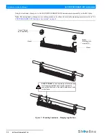
3. Connecting to the DMX512 Network
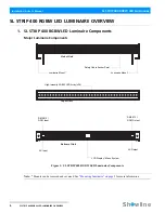
Basic DMX512 installation consists of connecting multiple SL STRIP 400 RGBW LED Luminaires together (up to
32 luminaires) in "daisy-chain" fashion. A cable runs from the control console (or DMX512 control source) to the
DMX connector on the first SL STRIP 400 RGBW LED Luminaire. Another cable runs from the other DMX
connector on the first unit to a DMX connector on the next SL STRIP 400 RGBW LED Luminaire (or DMX512
device to be controlled).
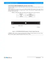
Figure 4: SL STRIP 400 RGBW LED Luminaire DMX512 Input / Output Connections
Note:
For more information on DMX512 networking and systems, refer to
"Additional Resources for DMX512" on
page 1
. For SL STRIP 400 RGBW LED Luminaire DMX Mapping, refer to
"DMX CONTROL" on page 16
.
Figure 5: SL STRIP 400 RGBW LED Luminaire - DMX512 Connections
Bottom of Unit
DMX512 / RDM Input
DMX512 / RDM Output
DMX512
DMX512
(out from first
to second luminaire)
DMX512
(out to the next
luminaire or DMX512
controlled device)
SL STRIP 400 RGBW
DMX512 Connections
Note: Remaining pins on each connector are not used.
DMX512 Signal
XLR Pin
Common (Drain)
1
DMX512 -
2
3
(from console or
control device)
LED Luminaires
Summary of Contents for SL Strip 400 RGBW Led Luminaire
Page 1: ......
Page 7: ...Installation User s Manual ...
Page 13: ......
Page 14: ......
Page 18: ...Installation User s Manual ...
Page 19: ...3 ...
Page 20: ...4 5 6 7 8 ...
Page 21: ...2 ...
Page 22: ...2 3 4 ...
Page 23: ...5 6 Installation User s Manual ...
Page 24: ...Installation User s Manual ...
Page 36: ......


