


ADM-880C 07/20/09
40
8.0 TEMPERATURE MEASUREMENT
8.1 TEMPROBE
Temperature measurements are obtained using the TemProbe temperature probe. The TemProbe may be plugged directly
into the temperature input jack on the back of the meter. Since this receptacle is keyed, the plug of the TemProbe sensor
must be correctly aligned for proper insertion. The release button on the side of the TemProbe must be pressed to
disconnect the TemProbe from the meter.
The “settling in” time required for the thermistor to stabilize at the temperature of the air being measured will vary with the
specifications of the TemProbe being used, the temperature differential between the TemProbe and the air, and also with
the velocity of the air across the probe. The “settling in” time is typically less than for a standard glass thermometer.
After turning the meter on, press the MODE key until [TEMP] is briefly displayed, followed by [
/
F READ]. Then, using the
retractile cord if necessary, place the TemProbe sensor in the medium to be sampled. Press the READ key to take a
temperature reading. If the TemProbe is not installed on the meter, or if it is open circuited (defective), the display will read
[NO PROBE].
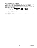
FIGURE 8.1 ADT442 TEMPROBE
The specified accuracy using the ADT442, ADT443, ADT444, ADT445 or ADT446 TemProbes is ± 0.5
/
F from 32
/
F to
158
/
F. Measurement range for the ADT-446 TemProbe is -20
/
F to 180
/
F. Measurement range for the ADT442, ADT443,
ADT444 or ADT445 TemProbes is -67.0
/
F to 250.0
/
F. Meter will display [OVER TEMP] or [UNDER TEMP] if the probe
is exposed to temperatures beyond this range. The maximum safe exposure range is -100
/
F to 250
/
F and the probe
accuracy may be affected by exposure beyond this range. Do not expose the plastic base of the TemProbe or the extension
wand to temperatures above 200
/
F.
NOTICE: The use of more than one temperature cable extender may reduce the meter reading by a non-linear degree
depending on the combination of cable type, length and TemProbe temperature. This is due to the added resistance of the
additional cable(s). This effect is likely to be negligible at very low temperatures, but may be
$
0.15
/
F per additional cable
extender at 154
/
F. The offset correction(s) must be determined by comparing readings taken with and without the extender
cables at the temperature(s) to be measured.
8.2 AIRDATA MULTITEMP
The MT-440K MultiTemp comes with six insertion probes, two surface probes, one eight-position switch, and a small
carrying case. The measuring capability of the MultiTemp combines with the memory function of the AirData Multimeter
to store up to 2000 temperature readings along with the sequence tag for each reading. Each temperature reading may
be entered into memory in two seconds or less. A full set of eight readings may be entered into memory in about 15
seconds.
Plug the single cord on the bottom edge of the MultiTemp into the temperature input jack on the back of the AirData
Multimeter. Up to eight temperature probes (each with a 12' cord) can be connected into the eight small, numbered
temperature input jacks on the top edge of the switch box. The jack numbers correspond to the eight switch position
numbers surrounding the switch. Place each of the temperature probes in the system as required and allow the probe
temperatures to stabilize. A typical system testing application is shown in Figure 8.2. Set the meter for the temperature
function as discussed in Section 5.0 USING THE AIRDATA MULTIMETER. Set the MultiTemp for switch position #1 and
take a reading for the probe connected to temperature input jack #1. Turn the switch to switch position #2 and take a
reading for temperature jack #2. Continue for as many of the eight temperature jacks as needed.
Summary of Contents for AIRDATA ADM-880C
Page 42: ...ADM 880C 07 20 09 37 FIGURE 6 3 VELGRID ASSEMBLY...
Page 50: ...ADM 880C 07 20 09 45 FIGURE 10 1 FRAME STORAGE FIGURE 10 2 FLOWHOOD IN CASE...
Page 51: ...ADM 880C 07 20 09 46 FIGURE 10 3 FLOWHOOD ASSEMBLY...
Page 53: ...ADM 880C 07 20 09 48 FIGURE 10 7 1X5 FRAME ASSEMBLY FIGURE 10 8 3X3 FRAME ASSEMBLY...


