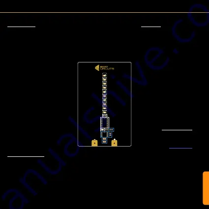
CIRCUIT
Circuit - NE555 Circuit
NE555 Timer IC (U1)
The NE555 is a very versatile chip that has
been around for 50 years. Some say the most
popular IC ever made...
The chip has 2 main operating modes:
1. Astable
In astable mode, the chip acts as an continu-
ous electronic oscillator. Common uses being
LED flashers, logic clocks, tone generators,
analog to digital conversion etc.
2. Monostable
In monostable mode, the chip produces one
pulse instead of a continuous oscillation once
triggered. The pulse ends when the capaci-
tor’s voltage reaches 2/3 of the supply voltage.
Any change to the trigger input will have no
effect on the output within the set timing inter-
val. This can be used to remove bounce from
switches, detect missing pulses, capacitance
measuring etc.
To provide a clock signal for the 4017 decade
counter, we are using the 555 timer in its as-
table mode.
Decoupling Capacitor (C1)
C1 is used to help smooth out variations in
the power supply that may cause the circuit
to malfunction. Capacitors take time to fill up
and empty. A bypass capacitor provides a res-
ervoir that adds voltage when some is missing
and absorbs some when extra is available.
R1, R2 and C2
The values of R1, R2 and C2 will determine the
frequency of the output clock signal.
The capacitor (C2) will charge up through R1
and R2 until it reaches 2/3 of the supply volt-
age. While this is happening, the output will be
high. When it reaches 2/3 of the supply voltage
it will start to discharge through R2 to the DIS
pin of the IC. This will cause the output to be
low. When the voltage of C2 reaches 1/3 of
the supply voltage, it will start charging again,
creating a continuous cycle.
Lowering the values of R1, R2 or C2 will in-
crease the frequency (speeding up the clock
pulse). Increasing their value will lower the
frequency.
You can use the following formula to calculate
the frequency:
Or head over to the
website to find some helpful calculators.
To get the desired frequency you can exper-
iment with the different value resistors and
capacitors found in the kit. Removing and
resoldering these will give you valuable solder-
ing and repair experience.
ƒ =
1.44
(R
1
+ 2R
2
)C
2
Summary of Contents for SABER CARD
Page 1: ...I N S T R U C T I O N M A N U A L SABER CARD v0 92...
Page 7: ...CIRCUIT Circuit Component Layout D2 R4 U2 D1 R1 R2 C1 C2 R3 U1 D3 D4 D5 D6 D7 D8 D9 D10 D11...
Page 13: ...ASSEMBLY D2 R4 U2 D1 R1 R2 C1 C2 R3 U1 D3 D4 D5 D6 D7 D8 D9 D10 D11...
Page 15: ...ASSEMBLY D2 R4 U2 D1 R1 R2 C1 C2 R3 U1 D3 D4 D5 D6 D7 D8 D9 D10 D11...


