Shop fox W1873 Owner'S Manual Download Page 20

-18-

Model W1873/W1874 (For Machines Mfd. Since 10/20)

SE

TU

P

Machine.Placement

Weight.Load

Refer to the 

Machine.Specifications

 for the 

weight of your machine. Make sure that the 

surface upon which the machine is placed will 

bear the weight of the machine, additional 

equipment that may be installed on the 

machine, and the heaviest workpiece that will 

be used. Additionally, consider the weight of 

the operator and any dynamic loading that may 

occur when operating the machine.
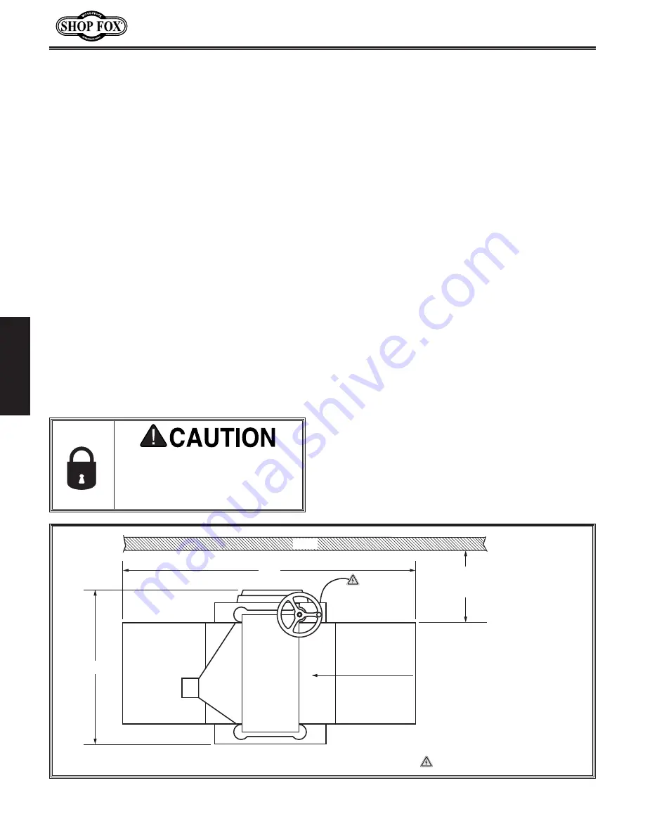
Space.Allocation

Consider the largest size of workpiece that 

will be processed through this machine and 

provide enough space around the machine 

for adequate operator material handling or 

the installation of auxiliary equipment. With 

permanent installations, leave enough space 

around the machine to open or remove doors/

covers as required by the maintenance and 

service described in this manual. 

See.below.for.

required.space.allocation.

Physical.Environment

The physical environment where your machine is 

operated is important for safe operation and the 

longevity of its components. For best results, 

operate this machine in a dry environment 

that is free from excessive moisture, hazardous 

chemicals, airborne abrasives, or extreme 

conditions. Extreme conditions for this type 

of machinery are generally those where the 

ambient temperature range exceeds 41°–104°F; 

the relative humidity range exceeds 20–95% 

(non-condensing); or the environment is subject 

to vibration, shocks, or bumps.

Electrical.Installation

Place this machine near an existing power 

source. Make sure all power cords are protected 

from traffic, material handling, moisture, 

chemicals, or other hazards. Make sure to leave 

access to a means of disconnecting the power 

source or engaging a lockout/tagout device.

Lighting

Lighting around the machine must be adequate 

enough that operations can be performed 

safely. Shadows, glare, or strobe effects that 

may distract or impede the operator must be 

eliminated.

Children. or. untrained. people.

may.be.seriously.injured.by.this.

machine..Only.install.in.an.access.

restricted.location.

Figure 8. Minimum working clearances for Models W1873 and W1874.

= Electrical Connection

25"

Feed Direction

Dust

Port

Min. 30"

for Maintenance

Wall

49"

Summary of Contents for W1873

Page 1: ...3482 Online Technical Support techsupport woodstockint com COPYRIGHT AUGUST 2019 BY WOODSTOCK INTERNATIONAL INC REVISED NOVEMBER 2020 MN WARNING NO PORTION OF THIS MANUAL MAY BE REPRODUCED IN ANY SHA...

Page 2: ...g grinding tool integrity and the usage of personal protective equipment The manufacturer will not be held liable for injury or property damage from negligence improper training machine modifications...

Page 3: ...ed Adjustments 23 OPERATIONS 24 Operation Overview 24 Workpiece Inspection 25 Wood Types 25 Planing Tips 26 Cutting Problems 26 Depth of Cut 28 Setting Feed Rate 29 Adjusting Replacing Knives W1873 29...

Page 4: ...questions arise about your machine please contact Woodstock International Technical Support at 360 734 3482 Ext 2 or send e mail to techsupport woodstockint com Our knowledgeable staff will help you...

Page 5: ...x 24 x 49 in Must Ship Upright Yes Electrical Power Requirement 230V Single Phase 60 Hz Full Load Current Rating 12A Minimum Circuit Size 20A Connection Type Cord Plug Power Cord Included Yes Power Co...

Page 6: ...tterhead Type Straight Knife Cutterhead Diameter 2 5 8 in Number of Knives 3 Knife Type HSS Single Sided Solid Knife Size Length 15 in Knife Size Width 1 in Knife Size Thickness 1 8 in Knife Adjustmen...

Page 7: ...Height 30 x 24 x 49 in Must Ship Upright Yes Electrical Power Requirement 230V Single Phase 60 Hz Full Load Current Rating 12A Minimum Circuit Size 20A Connection Type Cord Plug Power Cord Included Y...

Page 8: ...e Helical Cutterhead Diameter 2 5 8 in Number of Cutter Rows 4 Number of Indexable Cutters 48 Cutter Insert Type Indexable Carbide Cutter Insert Size Length 15mm Cutter Insert Size Width 15mm Cutter I...

Page 9: ...ontrols and features shown below to better understand the instructions in this manual To reduce your risk of serious injury or damage to the machine read this entire manual BEFORE using machine Gearbo...

Page 10: ...ock to accommodate different workpiece thicknesses One complete revolution moves the headstock approximately 5 32 4mm B Feed Rate Control Knob Selects 28 FPM feed rate when pushed in and 16 FPM feed r...

Page 11: ...G E F Front Rear Figure 2 Workpiece path and major planing components side cutaway view A Anti Kickback Fingers Provide additional safety for the operator B Serrated Infeed Roller Pulls the workpiece...

Page 12: ...rugs or alcohol when tired or when distracted ELECTRICAL EQUIPMENT INJURY RISKS You can be shocked burned or killed by touching live electrical components or improperly grounded machinery To reduce th...

Page 13: ...educe accidental contact with moving parts or flying debris make sure they are properly installed undamaged and working correctly FORCING MACHINERY Do not force machine It will do the job safer and be...

Page 14: ...s free of nails staples loose knots or foreign material Workpieces with minor warping should be jointed first or planed with the cupped side facing the table BODY PLACEMENT Stand to one side of planer...

Page 15: ...e full load current rating is the amperage a machine draws at 100 of the rated output power On machines with multiple motors this is the amperage drawn by the largest motor or sum of all motors and el...

Page 16: ...must only be inserted into a matching receptacle see Figure that is properly installed and grounded in accordance with local codes and ordinances For 230V Connection The machine must be properly set...

Page 17: ...aightedge 4 1 Dust Collection System 1 4 Dust Hose 1 4 Hose Clamp 1 Gearbox Oil Varies Wrench or Socket 12mm 17mm 1 Ea Wrenches or Sockets 13mm 2 Wrench or Socket 10mm 1 Hex Wrench 4mm 1 Items Needed...

Page 18: ...ure 5 E Hex Bolts M8 1 25 x 25 Ext Tables 6 F Button Head Cap Screws M6 1 x 12 6 G Set Screws M8 1 25 x 20 Ext Tables 6 H Hex Wrench 4mm 1 I LOW HIGH Direction Label Handwheel 1 J Hex Nut M10 1 25 Han...

Page 19: ...surfaces If your cleaner degreaser is effective the coating will wipe off easily Tip An easier way to clean off thick coats of rust preventative from flat surfaces is to use a PLASTIC paint scraper to...

Page 20: ...t for safe operation and the longevity of its components For best results operate this machine in a dry environment that is free from excessive moisture hazardous chemicals airborne abrasives or extre...

Page 21: ...ews into each extension table at locations shown in Figure 9 3 Using a straightedge as a guide rotate set screws until extension tables are in plane with main table then fully tighten hex bolts instal...

Page 22: ...tor To determine the CFM at the dust port you must consider these variables 1 CFM rating of the dust collector 2 hose type and length between the dust collector and the machine 3 number of branches or...

Page 23: ...of a clean 6mm hex wrench inside fill hole and then remove it If the end of the hex wrench is coated with oil then the gearbox oil level is okay Replace the fill plug and continue setup If the end of...

Page 24: ...laced before further using the machine Call Tech Support for help Test Run Once assembly is complete test run the machine to ensure it is properly connected to power and safety components are function...

Page 25: ...y step instructions for these adjustments can be found in the SERVICE section starting on Page 39 Factory adjustments that should be verified Tensioning replacing V belt Page 39 Calibrating headstock...

Page 26: ...ed rollers control feed rate of workpiece as it passes through planer Operator should not push or pull on workpiece If cut is too deep and bogs down planer operator immediately reduces depth of cut Th...

Page 27: ...chine Excess moisture can also hasten rust and corrosion of the machine and or individual components Excessive Warping Workpieces with excessive cupping bowing or twisting are dangerous to cut because...

Page 28: ...aner Always flatten cupped or warped workpieces on a jointer before planing Below is a list of wood characteristics you may encounter when planing The following descriptions of defects will give you s...

Page 29: ...tion Use a proper dust collection system adjust chip deflector in or out as necessary Workpiece must be completely dry preferably kiln dried KD Air dried AD lumber must be seasoned properly and have n...

Page 30: ...Although the correct depth of cut varies according to wood hardness and workpiece width we recommend the maximum depth of cut per pass be no more than 1 16 A series of light cuts will give better end...

Page 31: ...e cuts Setting the height of the knives correctly is crucial to the proper operation of your planer and is very important in keeping the knives sharp If one knife protrudes higher than the others it w...

Page 32: ...expose cutterhead 3 Put on heavy leather gloves 4 Remove belt cover then rotate cutterhead pulley to provide access to one of the knives 5 Loosen cutterhead gib bolts until knife is completely loose...

Page 33: ...y alternating left and right as illustrated in Figure 22 7 Insert hex wrench into access holes in cutterhead see Figure 20 and rotate jack screws to raise or lower knife until it barely touches center...

Page 34: ...1 Torque Wrench 1 T 20 Torx Bit 1 Heavy Leather Gloves 1 Pair Light Machine Oil As Needed The carbide inserts are very sharp and can quickly cut your hands ALWAYS use caution and heavy leather gloves...

Page 35: ...d replace insert with a new one Always position new insert reference dot in same position to aid in rotational sequencing 7 Lubricate Torx screw threads with a very small amount of light machine oil w...

Page 36: ...ars chip breakers and bed rollers Also a great setup tool for other machines Accurate to 0 001 Indicator rotates 360 D4112 Fractional Digital Caliper 6 Large LCD readout converts to decimal inch fract...

Page 37: ...piral cutterhead systems and made to last up to 10 times longer than a set of HSS steel inserts Made of solid carbide Size 15 x 15 x 2 5mm Figure 31 H9893 Indexable Carbide Inserts For W1873 D3635 15...

Page 38: ...uum excess wood chips and sawdust and wipe off the remaining dust with a dry cloth If any resin has built up use a resin dissolving cleaner to remove it Protect the unpainted cast iron table by wiping...

Page 39: ...in coat of ISO 68 machine oil to the outside surface of the columns and brush on a light application of multi purpose grease to the leadscrew threads Move the headstock up and down to distribute the l...

Page 40: ...ase to the chain and sprockets Gearbox Oil Oil Type ISO 320 Oil Amount 20 Oz Frequency After First 20 Hours Then Yearly Note We recommend that you replace the gearbox oil after the first 20 hours of o...

Page 41: ...damaged replace it Tensioning Replacing V Belt Items Needed Qty Hex Wrench 4mm 1 Hex Wrench 6mm 1 To tension replace V belt do these steps 1 DISCONNECT MACHINE FROM POWER 2 Remove side panel and belt...

Page 42: ...Note V belt is correctly tensioned when there is approximately 1 2 deflection when moderate pressure is applied to them midway between pulleys as illustrated in Figure 41 3 If V belt needs to be repl...

Page 43: ...d to achieve accurate results Note The chip breaker is spring mounted which allows it to adjust automatically to the workpiece No adjustment is necessary Distance Below Knife Insert at BDC Figure 42 A...

Page 44: ...tor dial from Step 5 repeat Steps 7 10 for outfeed roller but adjust it until it is 0 020 below BDC of cutterhead knife 12 Re install belt cover top cover and gearbox cover Figure 44 Example of infeed...

Page 45: ...ollers at same level as knife insert at BDC 9 Loosen jam nuts and set screws on each side of infeed roller see Figure 46 10 Using a feeler gauge adjust set screw so it is 0 040 from roller bushing blo...

Page 46: ...ion keep the following in mind If you are planing milled lumber with a consistent surface use less spring tension to reduce the risk of marring the workpiece If you are planing rough lumber with incon...

Page 47: ...gap to correct setting 5 Re tighten flange bolts then replace belt cover top cover and dust port Positioning Chip Deflector Items Needed Qty Wrench or Socket 10mm 1 Chip Deflector Gap Setting 1 16 1...

Page 48: ...are an important safety feature of your planer The fingers hang from a rod suspended across the head casting and in front of the infeed roller as shown This design allows the workpiece to easily enter...

Page 49: ...prockets It can be very difficult to return chain to its proper location on sprockets without changing table adjustments To adjust headstock height chain tension do these steps 1 DISCONNECT MACHINE FR...

Page 50: ...y adjusting how the headstock is mounted on the columns for movements under 0 008 When making adjustments tighten fasteners after each step to ensure the accuracy of your tests When adjusting the chai...

Page 51: ...e is adjusted equally 5 Mark location of one tooth of sprocket that you are adjusting 6 Carefully rotate sprocket clockwise to lower table counterclockwise to raise table just enough to position next...

Page 52: ...push idler wheel against chain with moderate pressure to eliminate slack in chain While maintaining pressure on idler wheel tighten hex bolt see Figure 55 4 Clean and lubricate chain and sprockets ref...

Page 53: ...points if available 12 Test repair replace Machine stalls or is underpowered 1 Machine undersized for task 2 Workpiece not suitable for machine 3 Motor overheated causing thermal overload to trip 4 Be...

Page 54: ...utting depth when planing hard woods 3 Slow down feed rate 4 Replace affected knife Page 29 or have it sharp ened rotate replace insert Page 32 Chipping indentation in workpiece sur face inconsistent...

Page 55: ...ng but it may not match your machine Always use the wiring diagram inside the motor junction box CAPACITORS INVERTERS Some capacitors and power inverters store an electrical charge for up to 10 minute...

Page 56: ...54 Model W1873 W1874 For Machines Mfd Since 10 20 SERVICE Electrical Components Figure 57 W1873 W1874 motor junction box Figure 56 W1873 W1874 magnetic switch with cover removed...

Page 57: ...15 NC21 SDE NC22 Ground RESET MAGNETIC SWITCH ASSEMBLY SDE MP 18 SDE MA 18 240V RA 20 B GND Start Capacitor 400MFD 125VAC 70uF 250VAC Run Capacitor MOTOR 230V Hot Hot Ground 6 20 Plug 230 VAC G motor...

Page 58: ...17 16 F 12 23 23 8 9 10 41 7 42 43 44 33 6 42 43 44 33 41 7 11 9 10 41 7 42 43 44 8 91 42 43 44 7 41 33 58 59 32 9 69 74 73 75 69 72 84 69 70 71 69 58 81 76 80 79 77 69 88 82 87 147 193 67 86 65 86 8...

Page 59: ...X1873073 SHAFT 27 X1873027 FLAT WASHER 6MM 74 X1873074 GEAR 27V2 X1873027V2 BUSHING V2 10 20 75 X1873075 KEY 5 X 5 X 10 28 X1873028 SET SCREW M6 1 X 30 76 X1873076 SHAFT 29 X1873029 HEX NUT M6 1 NYLO...

Page 60: ...195 144 154 156 153 A D 155 162 122 120 122 132 156 153 123 135 143 132 154 139 114 125 160 146 127 126 136 121 121 196 139 155 143 196 155 153 115 131 155 154 107 133 108 109 110 111 106 148 157 158...

Page 61: ...8 HEX WRENCH 4MM 122 X1873122 FLAT WASHER 10MM PLASTIC 149 X1873149 BELT COVER 123 X1873123 GAS STRUT 150 X1873150 MOTOR PLATE 124 X1873124 STAND 151 X1873151 BUTTON HD CAP SCR M6 1 X 20 125 X1873125...

Page 62: ...26 227 D 208 221 294 221 294 216 219 221 294 293 296 297 200 298 299 201 202 203 210 298 299 201 202 203 209 246 211 246 205 204 295 E E 208 207 245 214 215 216 217 218 221 222 212 223 224 225 206 210...

Page 63: ...E 3 216D X 10B K X M10 1 5 226 X1873226 HEX BOLT M8 1 25 X 25 207 X1873207 KEY 4 X 4 X 20 227 X1873227 SET SCREW M8 1 25 X 20 208 X1873208 SET SCREW M10 1 5 X 12 245 X1873245 REVOLVING HANDLE 24 X 92...

Page 64: ...tockint com to order new labels 301 302 303 304 305 306 307 308 309 310 311 312 REF PART DESCRIPTION REF PART DESCRIPTION 301 X1873301 READ MANUAL LABEL 307 X1873307 INJURY HAZARD LABEL 302 X1873302 M...

Page 65: ......

Page 66: ......

Page 67: ...e product This is Woodstock International Inc s sole written warranty and any and all warranties that may be implied by law including any merchantability or fitness for any particular purpose are here...

Page 68: ......

Reviews: