Shinko JC-33A Instruction Manual Download Page 2


Connector: 

D-sub connector 9-pin 

        Connection: RS-232C            RS-485 (Data transfer rate: 2400, 4800, 9600, 19200bps) 


  (Fig.2-2) 


Shield wire 

Connect only one side of the shield wire to the FG or GND terminal so as not to allow current to   

flow into the shield section. 

                If both sides of the shield section are connected to the FG or GND terminal, closed circuit will be 

made between the shield wire and the ground. 


As a result of this, current will run in the shield wire and 

the current may cause noise.


                Never fail to ground FG or GND terminal. 


Terminator 

        Do not connect terminator onto the communication line, because each of the JCS-33A, JCR-33A 

and JCD-33A has a built-in terminator. 

IF-300-C5 (sold separately) is available as a communication converter.


3. Setting the instruments 

• 

It is necessary to set the instrument number individually to the instruments when plural


units are connected in serial communication (Option: C5). 

Select the data transfer rate of the JC      series in accordance with that of the host computer. 


• 

Refer to the

 JCS

-33A, JCR-33A and JCD-33A instruction manual as for instrument number setting   

and transfer rate selection. 
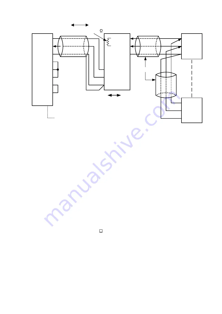


RXD

TXD

DCD

DTR

DSR

RTS

CTS

2

3

5

1

4

6

7

8

Host computer

D-sub connecter 9-pin

(6)

(7)

(8)

(14)

(15)

(16)

YA(-)

YB(+)

COM

RX

TX

COM

IF-300-C5

Built-in terminator 120

GND

RI

9

Shield wire

JCS-33A

RS-232C

RS-485

Shield wire

(13)

YB(+)

YA(-)

COM

(14)

(15)

(13)

YB(+)

YA(-)

COM

(14)

(15)

Summary of Contents for JC-33A

Page 1: ...n Option C5 Fig 1 1 Fig 1 2 Wiring connection When communication converter IF 300 C5 RS 232C is used Connector D sub connector 25 pin Connection RS 232C RS 485 Data transfer rate 2400 4800 9600 19200bps Fig 2 1 RS 485 Host computer No 0 JC 33A No 1 No 2 No 30 JC 33A JC 33A JC 33A RS 485 RS 232C Host computer 232C Communication IF 300 485 No 0 converter No 1 No 30 JC 33A JC 33A JC 33A TXD RXD SG FG...

Page 2: ...tion line because each of the JCS 33A JCR 33A and JCD 33A has a built in terminator IF 300 C5 sold separately is available as a communication converter 3 Setting the instruments It is necessary to set the instrument number individually to the instruments when plural units are connected in serial communication Option C5 Select the data transfer rate of the JC series in accordance with that of the h...

Page 3: ...er side Notice of making a program Set the program so that the host computer can provide 1 character transmission period or more of idle status mark status before sending the command to ensure the synchronization on the receiving side when the host computer starts the transmission to RS 485 communication line Set the program so that the host computer can disconnect the transmitter from the communi...

Page 4: ...de to indicate the end of command 03H fixed Error code Indicates error type Composed of hexadecimal 1 digit 1 31H Non existent command 2 32H Not used 3 33H Out of the setting value range 4 34H Status unable to set e g AT is performing 5 35H In setting mode by key operation 5 2 Checksum calculation Checksum is used for detecting received command or data errors Make a program for the host computer s...

Page 5: ...ble of this manual as for communication command All commands are written in ASCII The data setting value is converted from decimal to a hexadecimal number and ASCII is used Negative numbers are represented by 2 s complement When the data setting value has a decimal point use the whole number as response omitting decimal point Reading command All commands are written in ASCII The data setting value...

Page 6: ... setting value and information of slaves 06 06H Setting to slaves Function code is used as a pointer whether it is a normal response acknowledgement or an error negative acknowledgement when the Slave returns responsive message to the Master When acknowledgement is returned original function code is returned with its response When negative acknowledgement is returned MSD of the original function c...

Page 7: ...epeat 3 and 4 until shifting 8 times 6 EX OR between the next data and X X 7 Same as 3 to 5 8 Repeat up to the last data 9 Create a message in the sequence from lower to upper orders of the calculated 16 bit data X 6 7 Message example ASCII mode 1 Reading of the instrument number address 1 and SV A request message from the master side Fig 6 7 1 A response message from slave side in normal status W...

Page 8: ...out of the setting range is returned as an content of error Slave address Function code Data item Error check LRC Delimiter Header 01H 06H 0001H 0064H Data 94H CR LF 1 2 2 4 4 2 2 Number of characters Slave address Function code Abnormal code Error check LRC Delimiter Header 01H 86H 03H 76H CR LF 1 2 2 2 4 2 Number of characters 3 5 idle characters Slave address Function code Data item Error check...

Page 9: ...limit setting Setting value 20H 50H 06H 03H 0014H SV low limit setting Setting value 20H 50H 06H 03H 0015H Sensor correction value setting Setting value 20H 50H 06H 03H 0016H Overlap Dead band setting Setting value 20H 50H 06H 03H 0017H Not used 20H 50H 06H 03H 0018H Scaling high limit setting Setting value 20H 50H 06H 03H 0019H Scaling low limit setting Setting value 20H 50H 06H 03H 001AH Decimal...

Page 10: ...760 4 S 0 to 1760 5 B 0 to 1820 6 E 200 to 800 7 T 199 9 to 400 0 8 N 200 to 1300 9 PL 0 to 1390 10 C W Re5 26 0 to 2315 11 Pt100 199 9 to 850 0 12 JPt100 199 9 to 500 0 13 Pt100 200 to 850 14 JPt100 200 to 500 15 K 320 to 2500 16 K 199 9 to 750 0 17 J 320 to 1800 18 R 0 to 3200 19 S 0 to 3200 20 B 0 to 3300 21 E 320 to 1500 22 T 199 9 to 750 0 23 N 320 to 2300 24 PL 0 to 2500 25 C W Re5 26 0 to 4...

Page 11: ...06H 00A1H Instrument info reading 0000 0000 0000 0000 215 to 20 20 digit Not used Always 0 21 digit Cooling function 0 No 1 Yes 22 digit A1 function 0 No 1 Yes 23 digit A2 function 0 No 1 Yes 24 digit Not used Always 0 25 digit Not used Always 0 26 digit Heater burnout alarm 0 No 1 Yes 27 digit LA Loop break alarm 0 No 1 Yes 28 to 215 digit Not used Always 0 1 When Lock 3 is designated the setting...

Page 12: ...her the data bit parity and stop bit of the host computer accord with those of the JC series The instrument number of the JC series coincides with that of the command The instrument numbers are duplicated in multiple JC series When communicating by RS 485 option C5 without IF 300 C5 communication converter make sure that the program is proper for the transmission timing Phenomenon Though it is abl...

Reviews: