background image


FreeScan UE Pro_ User Manual _V1.2.2                                                                                                                                                  23 


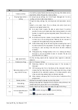
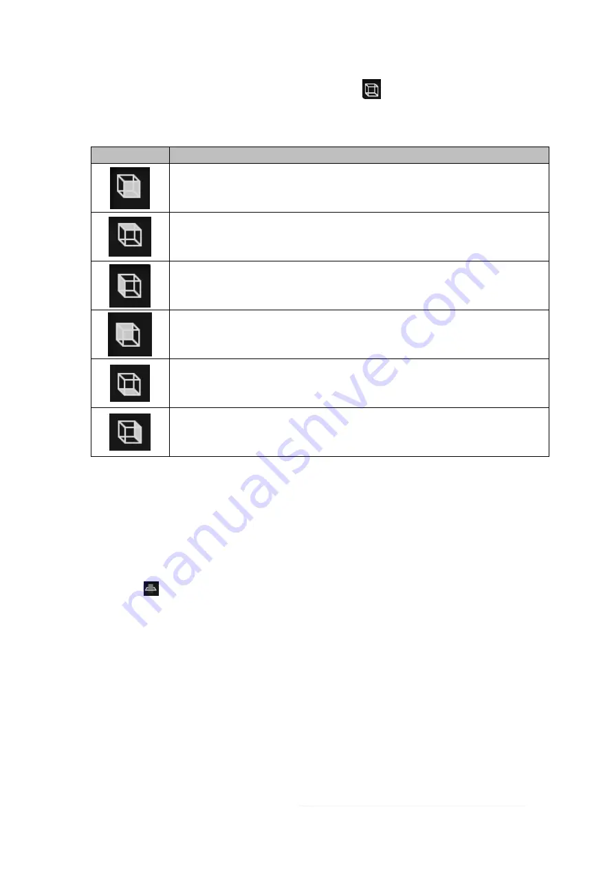
Alternatively, select the perspective selecting button, click 

  located at the bottom of the interface, 

and select different previews under various perspectives. 

Introduction to perspective adjustment 

Icon 

Description 


Front view, viewing the object to be scanned from the front perspective. 


Top view, viewing the object to be scanned from the top perspective. 


Left view, viewing the object to be scanned from the left side perspective. 


Back view, viewing the object to be scanned from the back perspective. 


Bottom view, viewing the object to be scanned from the bottom perspective. 


Right view, viewing the object to be scanned from the right-side perspective. 

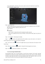
Create a Cutting Plane


After setting the cutting plane, the cutting plane above the direction of the arrow is valid (displayed in blue). The us
er can choose whether to save the data in the reverse direction (displayed in red) or delete it. Although the data in 
the reverse direction of the arrow can also be saved, the newly scanned data cannnot be added to it. 

Step 1      Click 

  and the cutting plane window pops out. 

Step 2      Choose how to create the cutting plane. 


Fitting Point Cloud

: the plane formed by the selected point cloud data is deemed as the cutting 

plane. 


Creating straight line

: draw a straight line on the object to be scanned, and the plane formed by such 

a straight line is deemed as a cutting plane. 


By Markers

: at least 3 markers shall be chosen and the plane formed by these 3 or more markers 

shall be deemed as the cutting plane. 

Step 3      Hold down Shift + LMB or select at least 3 markers to create a cutting plane. 

Summary of Contents for FreeScan UE Pro

Page 1: ...FreeScan UE Pro_ User Manual _V1 2 2 1 FreeScan UE Pro User Manual V1 2 2 ...

Page 2: ...form The Manual is a guidance for installing operating and maintaining the product including the Device software or other products provided by the Company to which the Manual is applicable The Manual does not serve as the quality guaranty for the product While the Company makes all efforts to ensure the applicability of the content of the Manual it reserves the right to interpret and modify the co...

Page 3: ...FreeScan UE Pro_ User Manual _V1 2 2 II information provided herein ...

Page 4: ... 3 OPERATION 8 3 1 WORKFLOW 8 3 2 CALIBRATION 8 3 2 1 Notes 8 3 2 2 Introduction to the Calibration Interface 9 3 2 3 Quick Calibration 9 3 3 CREATE A PROJECT 10 3 4 SCAN 11 3 4 1 Preparation 14 3 4 2 Preview 15 3 4 3 Parameter Setting 16 3 4 4 Point Cloud Scanning 17 3 4 5 Partial HD Scanning 18 3 4 6 Scanning Global Markers 19 3 4 7 Photogrammetry 20 3 4 8 Project Management 21 3 4 9 Edit Data 2...

Page 5: ...Holes 35 3 5 6 Cutting Plane Tool 37 3 6 MEASUREMENT 37 3 6 1 Create Feature 38 3 6 2 Align 39 3 6 3 Measure 41 3 7 SAVE 43 3 7 1 Save Data 43 3 7 2 Share Data 45 3 7 3 Third party Software 45 3 7 4 Preview Model 46 3 8 OTHER OPERATIONS 47 CONTACT US 49 ...

Page 6: ...ion Besides the device supports repeatable high precision operations without discrimination on the material and color of the objects to be scanned Therefore black or reflective surfaces are still scannable This device is mainly used in industries such as automobile industry transportation aerospace mold inspection and machinery manufacturing 1 2 Appearance Read the content on the yellow sticker ca...

Page 7: ...view Scanning Scanning paused 5 Scanning button Single click Prescan scan pause Press and hold Generate point cloud 6 Scanning distance indicator 1 3 Connect Cables Step 1 Connect aviation cable 4 to power port 2 and USB port 1 on the Scanner Step 2 Connect power cord 6 and the power adapter 5 Step 3 Connect power adapter 5 into aviation cable 4 Step 4 Connect USB port 3 on the aviation cable to t...

Page 8: ...FreeScan UE Pro_ User Manual _V1 2 2 3 Attention Ensure that cables are not loose during the above operations You are suggested to use fastening tools to prevent the device from being offline ...

Page 9: ...creased scanning frames The device is only compatible with Windows 10 Mac is not available for now 2 3 Installment Notes Before installing the software plug the dongle into the USB port of the computer for authentication of the encrypted software Open the USB flash drive and copy the installation package onto the computer Then install the software according to the indication Attention Do not insta...

Page 10: ...e Activation If the PC cannot be networked activate the Scanner offline Step 1 Export C2SN3D file Prepare a USB flash drive or portable hard disk 1 Insert the dongle to your PC 2 Enter the device serial number 3 Click Export And save the C2SN3D file to a USB flash drive Step 2 Upload C2SN3D file 1 Find a networked computer and enter https passport shining3d com login Then log in or register a new ...

Page 11: ... firmware If the firmware does not match the software will prompt you to upgrade the firmware as shown in the figure below Click Yes to upgrade Notes After clicking Yes to upgrade the software will be shut off automatically The upgrade takes about 5 minutes 2 5 2 Upgrade Software Software upgrade is to better meet the needs of users by downloading patches to optimize software performance or append...

Page 12: ...cally download the installation package in the background Do not close the software during the download When the download is completed a window automatically pops up for users to decide whether the new version shall be installed immediately Click Yes to start installing the new updates ...

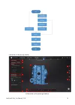
Page 13: ...t is the first time you operate the system refer to the following process Figure 3 1 Operation flowchart 3 2 Calibration Through calibration the device parameters are recalculated which not only ensures the accuracy of the Device but also improve the quality of its scanning 3 2 1 Notes Preparations before calibration Note To get higher accuracy please start to calibrate when the temperature of the...

Page 14: ...ay from corrosives metals and sharp objects to avoid corrosion or damage It is not recommended to wipe the calibration board When cleaning the board becomes very necessary gently wipe it with a piece of a clean damp cloth Do not use a cloth with chemicals or alcohols to wipe the calibration board After using the calibration board put it in a flannel bag 3 2 2 Introduction to the Calibration Interf...

Page 15: ...ndow click New project group and the window of creating new projects will pop up Step 2 Create a new folder or select an existing folder as the path for the storage of the project data The folder name is the same as the project name Step 3 Enter the resolution setting window where High Detail Medium Detail or Low Detail can be selected for default resolution options alternatively the slider can be...

Page 16: ...lity These devices can be used in the complex environments and spaces for scanning and directly and completely acquire the 3D data of physical objects with various sizes Then the scanners can quickly reconstruct the 3D model of the projects as well as various geometric data concerning the points lines surfaces and solids 3D data of the objects surfaces are obtained in form of point clouds which is...

Page 17: ...FreeScan UE Pro_ User Manual _V1 2 2 12 Introduction to the scanning interface Introduction to the scanning interface ...

Page 18: ...is high Targeted scanning can save scanning time and make the data obtained completer Photogrammetry Photogrammetry refers to a scanning technique that uses a scar bar and DSLR camera to measure the size and spatial position of an object 4 High speed mode On the scanning speed will be improved only supports 6 diameter markers 5 Parameter settings See 3 4 3 Parameter Setting 6 Remaining memory CPU ...

Page 19: ...models If the device fails to catch markers it will not emit laser lines Attach the markers evenly and randomly Four markers are required for the alignment at communal areas Ensure that the device s camera can scan at least 4 markers within the normal scanning range Please attach markers smaller than 3mm on the edges and or at small facets of the model Do not attach the markers on the surface with...

Page 20: ... through previewing and adjusting the parameters Click on the right side of the interface or press the Scan button on the Device to enter the preview mode Notes Under the preview mode model data are not collected The preview mode can be switched on after operations such as creating a new project importing a project pausing scanning and finishing scanning Click or press the Scan button on the Devic...

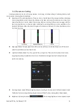
Page 21: ...dle of the Device When the indicator is green the distance is the best if it is blue the distance is too far if red too close Too close Suitable distance Too far High speed Mode The high speed mode of the scanner will lose some details Please turn off the mode when the point distance is less than 0 1mm Light Source Mode Select Cross lines parallel lines or single line There are 13 cross laser line...

Page 22: ...stem these points are defined by values on axis X Y and Z and are used to identify the external surface of the objects to be scanned When the device scans a large number of markers on the surface of an object it acquires a point cloud data file Users can obtain a large amount of point cloud data by scanning an object which is convenient for the subsequent model rendering and measurement Attention ...

Page 23: ...ng mode for a rescanning of that area Alternatively after importing a data file if a user finds that some data is missing he can also select this mode for a rescan Step 1 After obtaining an object s data through the point cloud scanning mode switch to the Partial HD Scanning mode Notes Under the Partial HD Scanning mode the light source mode will automatically be switched to 5 lines which can be c...

Page 24: ...he right hand side of the interface or press Scan button on the Device to enter the preview mode The scanning parameters are adjustable Step 7 Start to scan Click located on the right hand side or press Scan button on the device to start fine scanning Step 8 After the scanning click located on the right hand side to generate point clouds Step 9 Click to save the scanned data in asc or p3 formats 3...

Page 25: ...an improve the accuracy of global markers data According to the size of the scanned object import suitable scale bar files and place the matching scale bar near the scanned object before starting the scanning Photogrammetry is recommended for objects longer than 1 5 meters Generally photogrammetry is suitable for measurements for big parts in industrial applications that require high accuracy Step...

Page 26: ... task and scanning will be performed according to the resolution and alignment mode of the imported project Project Management Users can create import remove and or delete projects After creating multiple projects projects can be created or opened under project group and the projects will be displayed in the project list In the scanning interface click Project Group in the upper left corner and th...

Page 27: ...ast project in the list i e the current project is deleted or removed the last project in the current list will become the current project which can perform scanning If the project under another path is opened and it has the same as the existing project in the list _1 will be added to the name of the opened project and such added numbers will be given in a numerical order to other projects sharing...

Page 28: ...ing Plane After setting the cutting plane the cutting plane above the direction of the arrow is valid displayed in blue The us er can choose whether to save the data in the reverse direction displayed in red or delete it Although the data in the reverse direction of the arrow can also be saved the newly scanned data cannnot be added to it Step 1 Click and the cutting plane window pops out Step 2 C...

Page 29: ...ane Delete a plane After clicking the scanned data below the plane will be deleted Invert After clicking the scanned data above the plane will be deleted Delete selected data check the box to delete the red area Reset cancel previous operation Step 6 Click Apply to save the edit and exit the cutting plane setting Edit Model Users can select data to edit the model at their own discretion Introducti...

Page 30: ...election is completed release the Shift or double click the left mouse button The selected area will be displayed in red Lasso After clicking hold down both Shift and LMB and the lasso will appear At this time move the cursor to select the area to be edited The selected area will be displayed in red Straight line After clicking hold down both Shift and LMB and move the cursor to draw a straight li...

Page 31: ...pace bar to quit the edit mode Attention After applying of data editing the data s initial state cannot be restored unless by reloading the initial file Shortcut Keys The objects to be scanned can be edited through shortcut keys Shortcut keys Instruction Hold down the left mouse button and move the cursor Rotate the model Hold down the middle mouse button and move the cursor Translate the model Ro...

Page 32: ...lete data collection When more than two project files are present in the project list and scanned point cloud data exist in those project files the project can be aligned Click on the right side of the interface to enter the project alignment interface Notes If there is a project that has not generated a point cloud click Align and the following prompt box will pop up If Continue is clicked the po...

Page 33: ...features of the data Manual Alignment Manual alignment refers to obtaining the initial position of the point cloud through three points For large scale point clouds the less precise manual alignment method can be selected The best matches of the selected points are calculated and alignment is realized through the best fitting of all the points from the floating viewport to the fixed viewport After...

Page 34: ...m the alignment operation Next step The aligned projects will be merged into a group which can be further aligned Cancel Undo the completed alignment Exit Exit the project alignment interface 3 4 11 Mesh Meshing is to convert the point cloud into a triangular mesh surface After meshing the model can be enlarged and any triangle surface can be manually selected for observation The data after mesh c...

Page 35: ... model To customize parameters turn off the function Filter Optimize data Filter Low Filter Med Remove small floating parts Remove small floating parts on the model Remove spikes Remove spike like data on the image edge Max triangles Set max plate number to get mesh model s triangle plate number is within configured plate number ...

Page 36: ... Without markers hole fill With markers hole fill Step 3 Click Apply to mesh the data 3 5 Post processing After the model data is meshed the software automatically switches to the post processing interface Alternatively users can directly click on the navigation bar to enter the post processing interface and import data Post processing can then be performed on the data including simplification mes...

Page 37: ...horough After selecting the front and back sides of the model will be simultaneously selected 3 5 1 Simplification After simplification the polygon numbers file size and level of detail of data will be reduced accordingly Set the ratio from 1 to 100 the default is 0 The comparison of detail between before simplification and after simplification at 70 simplify proportion Simplification menu Click A...

Page 38: ...e original data Before simplification After simplification 3 5 2 Mesh Optimization Mesh optimization can optimize the quality of the data There are 3 ratio options of mesh optimization Processing time will be different Below shows the result of 3 different ratios Original Mesh optimization 10 Mesh optimization 50 Mesh optimization 100 ...

Page 39: ...oth the possible noise on the surface of the scan data It might remove some small details or smooth some sharp edges at the same time The example of before and after smoothing is shown below Run 2 times data will be smoothed twice Smooth menu Original Smooth 10 Smooth 50 Smooth 100 Click Apply to smooth data preview the result of current setting Click Confirm to apply the Smooth setting Click Canc...

Page 40: ...ting part the result will not be added It will always operate on the original data 3 5 5 Fill Holes Due to the loss of point cloud data in some areas holes may occur after the 3D scanned model is meshed resulting in incomplete models The model can be made complete through the hole mending operation Holes can be mended either automatically or manually Each method realizing hole mending according to...

Page 41: ...ates the solution considering the point position and the normal of the 2 last rows of triangles forming the boundary Effect of Curvature Tangent or Flat Click Apply to auto fill hole preview the result of current setting Click Confirm to apply the Auto hole filling setting Click Cancel to quit and go back to the original data Manual Hole Filling The hole edges are displayed green and get red after...

Page 42: ...g Reverse Selection the scanned data in the forward direction of the plane is in red Delete the selection and close the intersection Delete the selection and close the intersection delete the red area and fill in the scan data that coincides with the created plane Delete selection Delete the red area 4 Click Apply to delete the red area 5 Click Orient Based On Plane the scanning model will be read...

Page 43: ... Click create to create a point Line Plane Interface Line and Plane should be created in advanced Click on the created line or select it on the dropdown Click on the created plane or select it on the dropdown The point generated is the intersection between the non parallel line and plane Feature creation failed Error code 9 The line is parallel to the plane Line Point Point Pick 2 points Click on ...

Page 44: ...ne previously created or select it from the drop down Click on the data to select a point or click on a feature point previously created In the Choice list select one of the elements to reselect it Feature creation failed Error code 6 the point selected belongs to the line Best Fit Press Shift LMB to select an area press ctrl LMB to unselect The plane generated is the position with the smallest de...

Page 45: ...original position Click OK to confirm the transformation Tips Start from data reposition offset to 0 0 0 Edit rotations prior to transformation Change the view normal to a reference plane to change the corresponding angle 3 2 1 Movement Prior to 3 2 1 movement the creation of a plane line not normal to the plane and point are required 3 2 1 movement plane line point alignment aligns the data by de...

Page 46: ... axis The projection of the line to the first plane will be parallel to the corresponding axis Select a Point in the drop down menu The data will be translated to match the point with the origin point coordinate 0 0 0 Click Align to perform the transformation Data after 3 2 1 movement Click Reset to cancel Click Apply to confirm the transformation 3 6 3 Measure Click measurement button to display ...

Page 47: ...the Area value of the selected data in mm 2 Redo the selection and click calculate again to update If Select Through is enabled the sum of the surface area of the selected area and the surface area projected to the corresponding surface will be calculated Surface area menu VOLUME This tool calculates the volume contains in a watertight mesh It returns the volume in mm 3 and the coordinates of the ...

Page 48: ...Enter exit the measurement interface Click the Measure button to enter the measurement interface and display the measurement menu click the button again to exit the measurement interface 3 7 Save 3 7 1 Save Data Save data Enter the file name and click the save button Export data ...

Page 49: ... not needed Post processing can be done through other software ASC whole piece Optimized point cloud scan asc Check the data Quick export no need for post processing for handheld scanning Post processing can be done through other software STL Mesh data scan stl 3D printing Reverse designing Compatible with most post processing software OBJ Mesh data scan obj scan jpg scan mtl Used in artwork 3D re...

Page 50: ... Verisurf Geomagic Design X Geomagic Essentials and Solid Edge SHINING 3D Edition are included Users can import scanned mesh data into the third party software with one click Geomagic Control X Export data to Geomagic Control X Mainly used for 3D inspection If the Geomagic Control X software has been installed clicking this button will open the Geomagic Control X software and import the mesh data ...

Page 51: ...esh data Solid Edge SHINING 3D Edition Export data to Solid Edge SHINING 3D Edition Mainly used for reverse design of mesh data Solid Edge SHINING 3D Edition is a 3D CAD software If Solid Edge SHINING 3D Edition has been installed clicking this button will open the Solid Edge SHINING 3D Edition and import the mesh stl data into Solid Edge SHINING 3D Edition 3 7 4 Preview Model Double click the Pre...

Page 52: ...icial Website Open the official website of Shining 3D to learn about the company s products and information Facebook Enter Shining 3D s facebook to view product introduction and other operations Support Platform Enter Shining 3D s support platform to view product introduction and other operations Advanced mode After checking this option the point distance can be selected as 0 05 when creating a ne...

Page 53: ...r Experience Enhancement Program you might not be informed with software updates automatically Factory Default All settings can be restored to the initial settings and the software will automatically restart Language A language selection window pops up allowing users to choose multiple languages About View related software release information contact information etc Open help mode Open the real ti...

Page 54: ... Co Ltd Hangzhou China Phone 86 571 82999050 Add No 1398 Xiangbin Road Wenyan Xiaoshan Hangzhou Zhejiang China 311258 EMEA Region SHINING 3D Technology GmbH Stuttgart Germany Phone 49 711 28444089 Add Breitwiesenstraße 28 70565 Stuttgart Germany Americas Region SHINING 3D Technology Inc San Francisco United States Phone 1 415 259 4787 Add 1740 Cesar Chavez St Unit D San Francisco CA 94124 ...

Reviews: