


56(61)
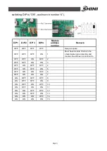
Next comes the setting on the control panel. Select and press buttons in
sequence: Function selection
—
System param. Setting
—
Password
(input)
—
System configuration:
1. Network module number: setting the number of modules composing system.
2. Water pump: equipped with the built-in pump or external pump. ON means
built-in pump and OFF means external pump.
3. Heat pump: units include single cool and heat pump models. ON means it is
heat pump and OFF single cool.
4. Auxiliary heat 1: indicate whether 1# module is equipped with auxiliary heat.
ON means connecting one and OFF no connecting.
5. Auxiliary heat 2: indicate whether 2# module is equipped with auxiliary heat.
ON means connecting one and OFF no connecting.
6. Module number for modularized configuration: module selected to be
ONLINE or not (set the module to be ONLINE running).
7. ONLINE setting: set the module to be ONLINE running. ON means module
online and it is activated in the unit while OFF means module offline and it is
idle in the unit (module is not applied to the unit for any fault, set it offline). 1#
module can not be OFFLINE.
Summary of Contents for SICC-120A
Page 1: ...SICC A Series Air cooled Central Water Chiller Date Apr 2013 Version Ver B English...
Page 2: ......
Page 8: ...8 61...
Page 13: ...13 61 Picture 1 2 Series Outline Dimensions SICC 90A...
Page 14: ...14 61 Picture 1 3 Series Outline Dimensions SICC 120A...
Page 16: ...16 61 Picture 1 5 SICC 60A Refrigerating Performance Curves...
Page 17: ...17 61 Picture 1 6 SICC 90A Refrigerating Performance Curves...
Page 18: ...18 61 Picture 1 7 SICC 120A Refrigerating Performance Curves...
Page 24: ...24 61 2 2 Electrical Diagram 2 2 1 Main Circuit SICC 60A Picture 2 2 Main Circuit SICC 60A...
Page 25: ...25 61 2 2 2 Control Circuit SICC 60A Picture 2 3 Control Circuit SICC 60A...
Page 28: ...28 61 2 2 5 Main Circuit SICC 90A Picture 2 5 Main Circuit SICC 90A...
Page 29: ...29 61 2 2 6 Control Circuit SICC 90A Picture 2 6 Control Circuit SICC 90A...
Page 32: ...32 61 2 2 9 Main Circuit SICC 120A Picture 2 8 Main Circuit 1 SICC 120A...
Page 33: ...33 61 Picture 2 9 Main Circuit 2 SICC 120A...
Page 34: ...34 61 2 2 10 Control Circuit SICC 120A Picture 2 10 Control Circuit SICC 120A...


