55(61)
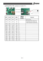
switching DIP to
“
ON
”
, as shown in number
“
4
”
).
DIP1 DIP2
DIP3
DIP4
Module
address
number
Remark
OFF
OFF
OFF
OFF
Keep as spare
OFF
OFF
OFF
ON
1
Must have module 1# which the
shared water pipe detecting and
devices has all been connected to
OFF
OFF
ON
OFF
2
OFF
OFF
ON
ON
3
OFF
ON
OFF
OFF
4
OFF
ON
OFF
ON
5
OFF
ON
ON
OFF
6
OFF
ON
ON
ON
7
ON
OFF
OFF
OFF
8
ON
OFF
OFF
ON
9
ON
OFF
ON
OFF
10
ON
OFF
ON
ON
11
ON
ON
OFF
OFF
12
ON
ON
OFF
ON
13
ON
ON
ON
OFF
14
ON
ON
ON
ON
15
Summary of Contents for SICC-120A
Page 1: ...SICC A Series Air cooled Central Water Chiller Date Apr 2013 Version Ver B English...
Page 2: ......
Page 8: ...8 61...
Page 13: ...13 61 Picture 1 2 Series Outline Dimensions SICC 90A...
Page 14: ...14 61 Picture 1 3 Series Outline Dimensions SICC 120A...
Page 16: ...16 61 Picture 1 5 SICC 60A Refrigerating Performance Curves...
Page 17: ...17 61 Picture 1 6 SICC 90A Refrigerating Performance Curves...
Page 18: ...18 61 Picture 1 7 SICC 120A Refrigerating Performance Curves...
Page 24: ...24 61 2 2 Electrical Diagram 2 2 1 Main Circuit SICC 60A Picture 2 2 Main Circuit SICC 60A...
Page 25: ...25 61 2 2 2 Control Circuit SICC 60A Picture 2 3 Control Circuit SICC 60A...
Page 28: ...28 61 2 2 5 Main Circuit SICC 90A Picture 2 5 Main Circuit SICC 90A...
Page 29: ...29 61 2 2 6 Control Circuit SICC 90A Picture 2 6 Control Circuit SICC 90A...
Page 32: ...32 61 2 2 9 Main Circuit SICC 120A Picture 2 8 Main Circuit 1 SICC 120A...
Page 33: ...33 61 Picture 2 9 Main Circuit 2 SICC 120A...
Page 34: ...34 61 2 2 10 Control Circuit SICC 120A Picture 2 10 Control Circuit SICC 120A...


