background image


33(40) 


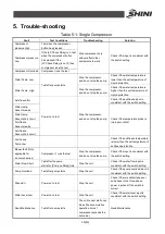
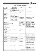
Fault 

Test Conditions 

Troubleshooting   

Solution   

Blower 1 fault


(Only applicable 
for air-cooled 
series)


Compressor 1 runs the test 

Stop the compressor,   

and do not stop the pump. 

Check  if  the  blower  1  fault  input 

input is consistent with the switch 

setting. 

Blower 2 fault


(Only applicable 
for air-cooled 
series)


Compressor 2 runs the test 

Check  if  the  blower  2  fault  input 

input is consistent with the switch 

setting. 

Blower 3 fault


(Only applicable 
for air-cooled 
series)


Compressor 3 runs the test 

Check  if  the  blower  3  fault  input 

input is consistent with the switch 

setting. 

Blower 4 fault


(Only applicable 
for air-cooled 
series)


Compressor 4 runs the test 

Check  if  the  blower  4  fault  input 

input is consistent with the switch 

setting. 

Water flow short 

Test after the pump starts for 

(Pump on delay)time 

Stop the unit   

Check  if  the  water  flow  input  is 

consistent with the switch setting 

Pump Overload 

Test after pump starts 

Stop the unit   

Check if the pump overload input 

is consistent with the switch 

setting. 

Phase Err 

Power on to test 

Stop the unit   

Check if there is default phase or 

anti-phase in the three-phase 

power input and if the switch is 

correct. 

Water Level Low 

Power on to test 

Stop the unit   

Check if the water level input is 

consistent with the switch 

setting. 

Need Maintenance 

Test after pump starts 

The unit connot start once stops(the accumulative operation time of 

compressor exceeds the set value) 


Summary of Contents for SIC-A

Page 1: ...SIC A Air cooled Water Chillers Date Mar 2022 Version Ver C English...

Page 2: ......

Page 3: ...nents and Functions 16 2 2 1 Compressor 16 2 2 2 Condenser 16 2 2 3 Drying Filter 16 2 2 4 Thermal Expansion Valve 17 2 2 5 Evaporator 17 2 2 6 High and Low Pressure Controller 17 2 2 7 Fluid Reservoi...

Page 4: ...ance 34 6 1 Filling the Refrigerant 36 6 2 Components Maintenance 37 6 2 1 Condenser 37 6 2 2 Evaporator 37 6 3 Maintenance Schedule 39 6 3 1 About the Machine 39 6 3 2 Check after Installation 39 6 3...

Page 5: ...vaporator 17 Picture 2 7 High and Low Pressure Controller 18 Picture 2 8 Fluid Reservoir 18 Picture 2 9 Refrigerant Indicator 19 Picture 2 10 Liquid Pipe Solenoid Valve 19 Picture 2 11 Hot gas By pass...

Page 6: ...r overload protection pump overload protection phase reverse alarm anti freezing protection high low pressure protector which features stable performance and long service life It can quickly cool down...

Page 7: ...of 0 1 All adopt branded compressors with low noise high efficiency and long service life SIC A adopts fin style condenser design without any need of cooling water for excellent heat transfer and rap...

Page 8: ...ions for the daily operator Any modifications of the machine must be approved by SHINI in order to avoid personal injury and damage to machine We shall not be liable for any damage caused by unauthori...

Page 9: ...0 174 1320 1 1 1 2 1 2 1 2 315 SIC 8A 1350 640 735 300 204 1610 11 2 11 2 1 2 1 2 1 2 400 SIC 10A 1440 640 735 300 204 1610 11 2 11 2 1 2 1 2 1 2 420 SIC 12 5A 1520 648 905 457 189 1780 2 2 1 2 1 2 1...

Page 10: ...ing Water Outlet 1 11 2 2 Cooling Water Inlet 1 11 2 2 Water Tank Outlet 1 2 Water Tank Port 1 2 Protective Devices Compressor Overload relay pump Overload relay Cooling Water Circuit High and low pre...

Page 11: ...21 2 Cooling Water Inlet 2 21 2 21 2 Water Tank Outlet 1 Water Tank Port 1 2 1 Protective Devices Compressor Overload relay pump Overload relay Cooling Water Circuit High and low pressure switch anti...

Page 12: ...the electrical control cabinet Warning Be careful Pay more attentions at the places where this sign is attached Attention Drain the water inside when power off at the cold day to avoid freezing Atten...

Page 13: ...careless or man made installations operation and maintenances upon machines without referring to the Manual prior to machine using 2 Any incidents beyond human reasonable controls which include man m...

Page 14: ...oid valve optional 7 Refrigerant indicator optional 8 Expansion valve 9 Evaporator 10 Anti freezing switch 11 Flow switch option 12 Water tank liquid sensor option 13 Temp sensor 14 Water tank 15 Floa...

Page 15: ...alue The low temperature gas refrigerant from the evaporator returns to the compressor which circulates in this way Hot gas bypass function when the temperature of chilled water reaches the set temper...

Page 16: ...2 2 2 Condenser 1 It is the heat output device which can discharge the heat absorbed by the refrigerant in the evaporator and the heat converted by the compressor consumption to the cooling medium 2...

Page 17: ...the refrigerant flow into the evaporator 2 The heat expansion valve is installed in front of the evaporator Picture 2 5 Thermal Expansion Valve 2 2 5 Evaporator 1 The evaporator is a device that outpu...

Page 18: ...ll give the alarm when the compressor outlet air pressure is higher than 25bar or the compressor suction port is lower than 2bar Picture 2 7 High and Low Pressure Controller 2 2 7 Fluid Reservoir 1 It...

Page 19: ...to detect the water ratio of the system 2 3 2 Liquid Pipe Solenoid Valve Picture 2 10 Liquid Pipe Solenoid Valve Cut off the refrigerant supply circuit immediately after shutdown to prevent the evapor...

Page 20: ...is adopted to avoid system damage caused by the cold water circulation failure of the water chiller 2 3 5 Liquid Level Indicator Picture 2 13 Liquid Level Indicator With the liquid level indicator it...

Page 21: ...elay can resume working Picture 2 14 Thermal Overlaod Relay The description of thermal overlaod relay 1 Setting current adjusting scale 2 Reset button blue H Manual reset A Auto reset 3 Release indica...

Page 22: ...urer s name plate 2 Connection cable and ground wire must abide by local rules and regulations 3 Use independent electrical wires and power switch and the diameter of electrical wire should not be sma...

Page 23: ...cooling tower is harsh the cooling water and chilled water loop must be equipped with the filters and cleaned regularly 13 The circulating circuit of chilled water shall be covered with insulation la...

Page 24: ...Cooling 3 Chilled water outlet 7 Cooling water pump 11 Cooling tank 4 Drain port 8 Cooling water circulation 12 Oil Cooling Picture 3 1 Machine Installation Location 3 3 Power Connection The SIC A ser...

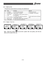
Page 25: ...een The system will enter the main screen after countdown which displays as follows 2 Alarm Screen In case of unit failure the alarm screen is as follows Commonly used screens include the main screen...

Page 26: ...creen will automatically pop up The operation details of query and reset faults are as follows Attention Pump rotating direction should be correct Attention Before starting the system make sure that c...

Page 27: ...s button to start the water pump 4 Press button to start the compressor 4 5 Shutdown 1 Turn off the switch of compressor 2 Turn off the pump switch If it adopts the quick molding cycle and low cooling...

Page 28: ...ration For the modification operation of parameter value the user s modification of setting temperature will be described as an example 4 6 2 User Setting All the parameters in user settings please re...

Page 29: ...rned off 3 Compr Use Time To query the cumulative operation time of the compressor 4 Comm Setting To set baud rate parity bit stop bit and communication address Communication protocol Modbus RTU 5 Mac...

Page 30: ...ter temp Sensor breaks Check if the temperature probe is in proper contact Water temp Sensor short circuit Anti freeze Sensor breaks Anti freeze Sensor short circuit Anti freeze Temp Low Check if the...

Page 31: ...he pump Check if the antifreeze input is consistent with the switch setting Water temp Sensor breaks Check if the temperature probe is in proper contact Water temp Sensor short circuit Anti freeze Sen...

Page 32: ...compressor button has pressed If the LP Check Delay is not 0 then compressor 3 runs the test Compressor 3 overload Compressor 3 runs the test Compressor 4 pressure high Test when the compressor butto...

Page 33: ...for air cooled series Compressor 4 runs the test Check if the blower 4 fault input input is consistent with the switch setting Water flow short Test after the pump starts for Pump on delay time Stop...

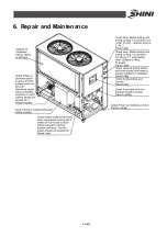
Page 34: ...34 40 6 Repair and Maintenance...

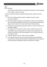
Page 35: ...don t start the machine forcibly before troubleshooting 3 Please check periodicaly to prolong the machine s service life and prevent the safety accident 4 The water used in the system must have water...

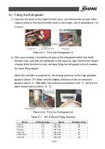
Page 36: ...nge of the electronic scale and stop filling the refrigerant when it reaches the rated filling weight When the machine is powered on the display pressure of the high pressure gauge is about 13 15bar a...

Page 37: ...r Attention Do the cleaning work every half year in the environment with little dust but you must do the work every month in the environment with a great deal of dusts and under the severe environment...

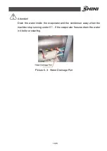
Page 38: ...Attention Drain the water inside the evaporator and the condenser away when the machine stop running under 0 If the evaporator freezes drain the water in it before restarting Picture 6 3 Water Drainag...

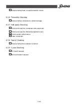
Page 39: ...ase sequence of power supply 6 3 3 Daily Checking Check switch functions Check all the electrical wires Check whether pressure gauges are accurate Check whether compressor temperature is normal Check...

Page 40: ...is under blockage 6 3 7 Half yearly Checking Check and clean the condenser and evaporator Check and clean the filter and expansion valve Check system performance Clean condenser 6 3 8 Yearly Checking...

Reviews: