background image

CAA-100 Series User’s manual 

Shineway Technologies, Inc. 


29-


Display Mode 

4 modes: 
Default: 
Black-white: used for printing 
High-contrast: 
Night vision: used in night environment 

Fan Mode 

Three modes: Auto; Always On; Always Off. 
The default is Always On. If temperature higher than 45 degrees ,fan is 

turned on; if below 35 degrees fan is turned off. 

Power Mode 

Two modes: standard modes(default); power saving mode 

If working in the power saving mode, the relative RF circuits will be 

power  on  until  measurement  .  It  can  save  power’s  consumption  and 
protect  circuits,  but  its  disadvantage  is  the  measurement  time  will  be  a 
little long. 

File management 

For file management of both local disk and the external disk 
Support file copy and delete functions 
Support  following  file  type  :measurement  data(.csv),  measurement 

image (.Jpg), calibration data (.csv) 

Touch screen Cal 

To calibrate the touch screen. Users Can exit by pushing any hard key   

Default 

Restore to default value 


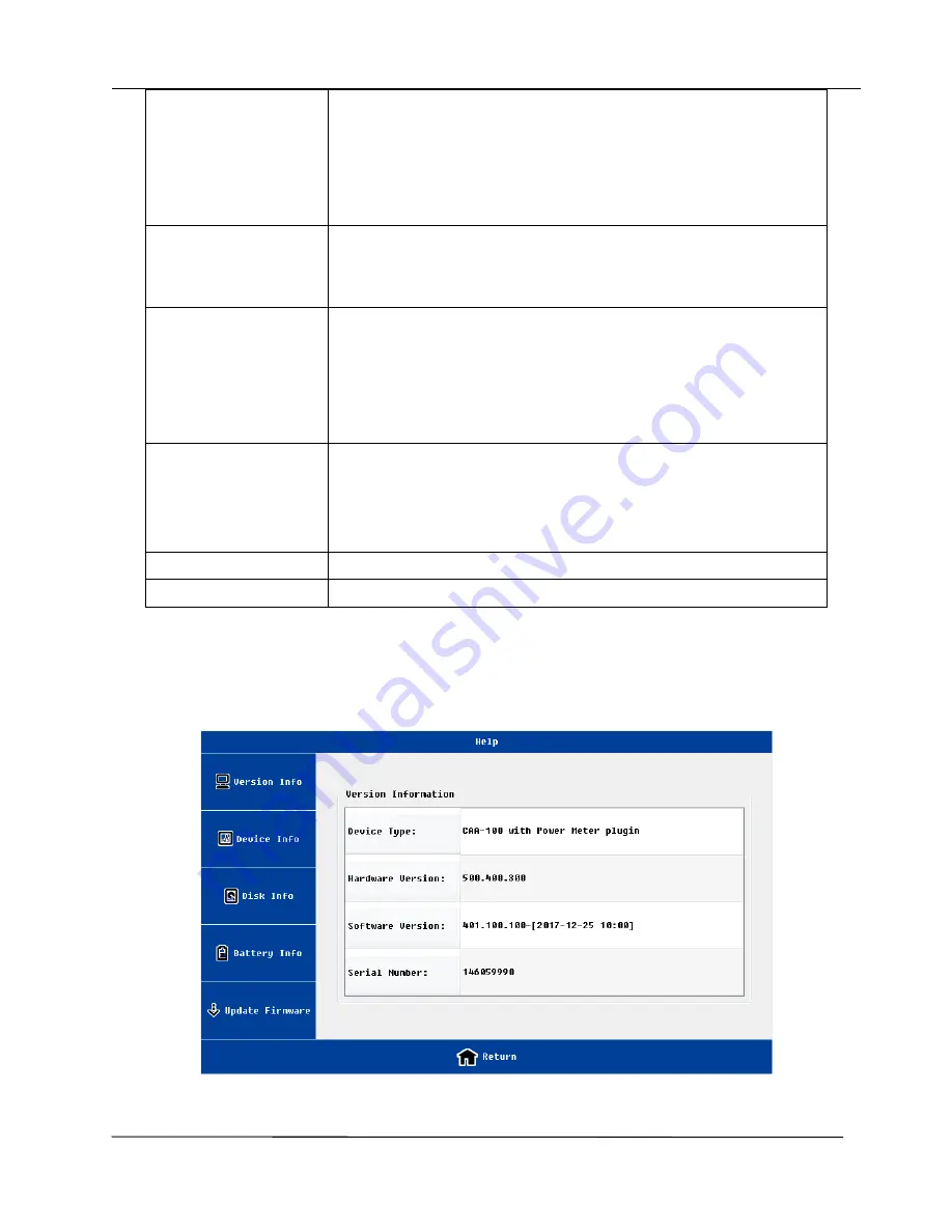
3.8 Help interface 


Version information interface 

Summary of Contents for CAA-100 Series

Page 1: ...CAA 100 Series Cable and Antenna Analyzer User s Manual...

Page 2: ...kes no warranty of any kind with regard to this material including but not limited to the implied warranties of merchantability and fitness for a particular purpose ShinewayTech shall not be liable fo...

Page 3: ...Environmental conditions It is designed to operate at a maximum relative humidity of 95 and at altitudes of up to 2000 meters Refer to the specifications tables Before applying power Verify that the p...

Page 4: ...cated conditions are fully understood and met The NOTE sign information that may be beneficial during the use and maintenance of the instrument Electrical safety precautions If you need to ensure that...

Page 5: ...of this Manual 1 1 2 Unpacking and Inspection 1 1 3Product Introduction 1 1 4 Features 1 2 The appearance introduction of equipment 2 2 1 The head cover 2 2 2 Front panel 3 3 User interface and menu...

Page 6: ...2 2 Set Cable parameter 35 4 2 3 Set Window Function 36 4 3 OSL Calibration 36 4 4 Freq Return Loss Freq VSWR Cable Loss measurement 38 4 5 DTF VSWR DTF Return Loss measurement 38 4 6 Smith Chart 38 4...

Page 7: ...ail support shinewaytech com When returns please Packing meter with soft material Use original case If not please fill at least 3cm soft material around the meter Correctly fill out and return the pro...

Page 8: ...earance introduction of equipment 2 1 The head cover The head cover contains a variety of interface A detailed description of the following No Name Icon Function and Description 1 RF connector To conn...

Page 9: ...nt and press it for 2s to turn off the instrument Description for indicator lights Position State Meaning Left Red Battery Charging green Battery Charge fully Right Off Power off green Power on red Me...

Page 10: ...face left and right move marker line Up and down move limit line Enter key Digital key input 0 9 key decimal point key Minus sign 3 User interface and menu instructions 3 1 Turn on the instrument Pres...

Page 11: ...urement modes DTF distance fault return loss DTF VSWR Frequency return loss Frequency VSWR cable loss Smith Phase and Power Meter Click the icon the system will go into the corresponding measurement i...

Page 12: ...later chapter 4 Message bar Left Frequency distance measuring points etc 5 Display area Middle For details see later chapter If the user wants to zoom in the display area can click the arrow or Nav k...

Page 13: ...o into DTF parameters menu more parameters and information will be included in this menu Display For details see later chapter Data Mem Save current data to memory Note only one data can be save to th...

Page 14: ...e main interface click Measurement Power Meter coin users will enter the RF Power Meter interface The steps and the interface are as shown below Users should connect the RF power meter to the unit fir...

Page 15: ...ycle RF Power Meter interface is main including the followings No Naming Location Description 1 Information status bar Left up connector Display parameter information 2 Test result display area Up RF...

Page 16: ...echnologies Inc 10 Frequency Band It is include build in frequency and user defined frequency For the user defined frequency users can input the frequency range is below DPM 50AP Frequency range 300M...

Page 17: ...Modulation signal modulation frequency is higher the time span should be smaller For burst signals or pulse signals the time span needs to be less than the minimum pulse width CCDF Threshold Before t...

Page 18: ...s can set the interval measure time and the total measure time Interval 1s 60s Total 2s 7200s The total time should be longer than the interval time Limit Users can set the limit power range and chose...

Page 19: ...13 Default Setting Users can load default parameters in this interface 3 5 The function menu description 3 5 1 Marker In all five measurement mode users can use mark function The user click marker men...

Page 20: ...so close all markers The user clicks on MX the MX marker automatically is activated The status will be shown on the top status bar Users click on the Edit menu the edit menu will show on the left side...

Page 21: ...supports difference marker relative to M1 users click on the MX M1 the system will go into the difference marker mode The status displayed in the status bar is the difference between X and Y direction...

Page 22: ...n Up and down arrow key of hard keyboard to fine adjust and define the location After the location of the limit line is determined users need to confirm the operation soft keyboard Enter key or hard k...

Page 23: ...setting menu Name function and description Default Y axis coordinate go back to the default value Return Loss 0 60 VSWR 1 65 Cable Loss 0 30 Auto Adjust Y axis automatically to adapt current measurem...

Page 24: ...coordinate can only be edited if manual menu is activated 3 5 4 File The user can save measurement data or picture to PC also can recall measurement data from PC to CAA 100 Series This function facili...

Page 25: ...CAA 100 Series User s manual Shineway Technologies Inc 19 Image preview interface File import interface...

Page 26: ...rmat The default file name includes the measurement mode frequency measuring points the time information users can choose to save in the local memory or external memory Only support measurement data S...

Page 27: ...t measured data and memory data Display menu Display setting menu Name function and description Data Mem Save current data to memory Note Only one data can save The data can be the current measurement...

Page 28: ...ing points the distance information etc Data Memory Display the current measuring data the memory data Note the format of two data must be same such as the mode of measurement frequency measuring poin...

Page 29: ...t point or not When users select the Flexcal the calibration is default the whole frequency range calibration and the measurement range is 551 When calibration is finished changing the frequency range...

Page 30: ...ser know the exact electrical length of open short load Users can input this parameters in the e parameter menu Is the electrical length of open and short cal kit same Is the exact electrical length o...

Page 31: ...eries User s manual Shineway Technologies Inc 25 3 7 System Settings Interface In the system settings interface users can do all kinds of system configuration Language setting interface Clock setting...

Page 32: ...CAA 100 Series User s manual Shineway Technologies Inc 26 Back light setting interface Display mode setting interface...

Page 33: ...CAA 100 Series User s manual Shineway Technologies Inc 27 Power mode setting interface...

Page 34: ...inserted before operating File Management 2 User must return to the superior interface before removing the external disk to make sure files performed Load default setting interface Name function and d...

Page 35: ...de If working in the power saving mode the relative RF circuits will be power on until measurement It can save power s consumption and protect circuits but its disadvantage is the measurement time wil...

Page 36: ...CAA 100 Series User s manual Shineway Technologies Inc 30 Device information interface Disk information interface...

Page 37: ...a variety of instruments information meanwhile users can upgrade the firmware Name function and description Version Info Includes hardware version software version instrument serial number etc Device...

Page 38: ...and other information Update Firmware The user insert the U disk to the instrument select the correct version file the instrument will automatically upgrade After the upgrade is complete the instrume...

Page 39: ...k on the parameter button In the frequency return loss or frequency VSWR or cable loss measurement interface click on the parameter button The user can also input frequency parameters in DTF parameter...

Page 40: ...on The minimum frequency interval is 1MHz The start frequency range is 25 3999MHz The stop frequency range is 26 4000MHz The user can modify the pre defined signal standard through PC software 4 2 Se...

Page 41: ...e the frequency if users want to increase the allowed cable length can increase the number of measuring points the corresponding test time can also be longer Due to the calculation of DTF the minimum...

Page 42: ...n is completed the cable parameters will automatically refresh in DTF parameter interface 4 2 3 Set Window Function In the distance to the fault analysis if the location of the two connectors are clos...

Page 43: ...ronic calibration is as the following step Set the frequency parameter and measurement point Select the Flexcal calibration Connect the electronic calibrator and USB cable to the unit Click the ECAL c...

Page 44: ...Loss measurement The measurement can be used to verify the power matching performance of different position of cable and antenna system then user know a certain position joint connection quality X axi...

Page 45: ...interface click Measurement Smith users can enter the Smith Chart interface Set parameter first and make sure the it is in Cal On status before measurement 4 7 Phase Phase can display the phase of th...

Page 46: ...r selected parts 5 2 Exclusions The warranty on your equipment shall not apply to defects resulting from the following Unauthorized repair or modification Misuse negligence or accident Shineway Techno...

Page 47: ...icient service 5 5 Contacting Customer Service Please check our web site www shinewaytech com for updates to this manual and additional application information If you need technical or sales support p...

Page 48: ...CAA 100 Series User s manual Shineway Technologies Inc 42 THANK YOU FOR CHOOSING SHINEWAY TECHNOLOGIES...

Reviews: