background image

SHINDAIWA OWNER’S/OPERATOR’S MANUAL

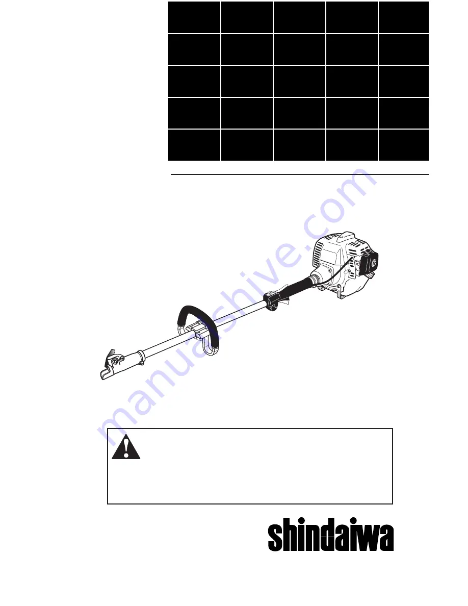
M231 MULTIPURPOSE 

TOOL CARRIER

M231

Part Number 65008-94011 Rev. 12/05

®


WARNING

!

Minimize the risk of injury to yourself and others! Read this manual 

and familiarize yourself with the contents. Always wear eye and 

hearing protection when operating this unit.

Summary of Contents for M231

Page 1: ...TIPURPOSE TOOL CARRIER M231 Part Number 65008 94011 Rev 12 05 WARNING Minimize the risk of injury to yourself and others Read this manual and familiarize yourself with the contents Always wear eye and...

Page 2: ...4 Operating Precautions 5 Product Description 6 Specifications 7 Assembly 8 Installing a Tool Attachment 9 Mixing Engine Fuel 10 Starting the Engine 11 Stopping the Engine 13 Adjusting Engine Idle 13...

Page 3: ...tention Statements IMPORTANT A statement preceded by the word IMPORTANT is one that possesses special significance NOTE A statement preceded by the word NOTE contains information that is handy to know...

Page 4: ...e vegetation mud etc ALWAYS hold the unit firmly with both hands when cutting or trimming and maintain control at all times ALWAYS keep the handles clean ALWAYS disconnect the spark plug wire before p...

Page 5: ...ty and Operation Information Labels Make sure all information labels are undamaged and readable Immediately replace damaged or miss ing information labels New labels are available from your local auth...

Page 6: ...are working properly WARNING Before starting the engine make sure the cutting attach ment is not contacting anything Always stop the engine imme diately and check for damage if you strike a foreign o...

Page 7: ...anding your unit helps ensure top performance long service life and safer operation See Figure 2 and 2a Handle Coupler Throttle Trigger Throttle Lockout Lever Tank Guard Figure 2 Ignition Switch Air C...

Page 8: ...EPA emission compliance referred to on the emission compliance label located on the engine indicates the number of operating hours for which the engine has been shown to meet Federal emission require...

Page 9: ...the screws finger tight ONLY at this time 3 Locate the handle in the best position for operator comfort usu ally about 10 inches ahead of the throttle assembly 4 Secure the handle by alternately tight...

Page 10: ...at sur face loosen the coupler screw knob The spring loaded coupler protector should pop up 2 Press down on the latch with your finger or thumb This releases the coupler lock See Figure 6 3 Pull the t...

Page 11: ...ng oil IMPORTANT Mix only enough fuel for your immedi ate needs If fuel must be stored longer than 30 days and oil with fuel stabilizer is not used it should first be treated with a fuel stabilizer su...

Page 12: ...sition if engine is cold Make sure the cutting head is clear of ob structions Primer Bulb Return Tube IMPORTANT Engine ignition is controlled by a two position switch mounted on the throttle housing l...

Page 13: ...t to stop turning If the cutting attachment continues to rotate when the engine returns to idle carburetor idle speed should be adjusted see the next page IMPORTANT If the engine fails to start after...

Page 14: ...he cutting attachment must NEVER rotate at engine idle If the idle speed cannot be adjusted by the procedure described here return the unit to your Shindaiwa dealer for inspection Idle Speed Adjustmen...

Page 15: ...engine to run at high RPM without a load Doing so could damage the engine NEVER operate a unit with worn or damaged fasteners or attachment holders NEVER operate the unit with the cutting attachment s...

Page 16: ...nd screws except carburetor adjusting screws are tight 15 MAINTENANCE WARNING Before performing any mainte nance repair or cleaning work on the unit make sure the engine and cutting attachment are com...

Page 17: ...g to prevent dirt and debris from falling into internal engine parts Clean the spark plug and check the gap at the electrode Every 10 hours of operation more frequently in dusty or dirty conditions Re...

Page 18: ...17 Remove and replace the filter element Before reinstall ing the filter inspect the condi tion of the fuel line If damage or deterioration are noted the M231 Multipurpose Tool Carrier should be remov...

Page 19: ...ffler 5 mm Muffler Screws Rear Muffler Shield Spark Ar rester Screen Rear Muffler Shield Screw Figure 18 MAINTENANCE 18 IMPORTANT If you note excessive carbon buildup consult with an authorized servic...

Page 20: ...Remove the spark plug and pour about 1 4 ounce of 2 cycle mixing oil into the cylinder through the spark plug hole Slowly pull the recoil starter 2 or 3 times so oil will evenly coat the interior of...

Page 21: ...t NO YES Is fuel visible and moving in the return line when priming Check for clogged fuel filter and or vent Clean as required restart NO Is there spark at the spark plug wire terminal The ignition s...

Page 22: ...speeds May also have black smoke and or unburned fuel at the exhaust Clogged air cleaner Loose or damaged spark plug Air leakage or clogged fuel line Water in the fuel Piston seizure Faulty carbureto...

Page 23: ...CJ8 or equivalent resistor type spark plug of the correct heat range Set spark plug electrode gap to 0 024 0 028 inch 0 6 0 7 mm For Electromagnetic compliance EMC use NGK BMR6A Restart Replace the i...

Page 24: ...damaged bushings Inspect and replace attachment as required Tighten gearcase securely Inspect and replace as necessary Cutting attachment will not rotate Shaft not installed in powerhead or gearcase B...

Page 25: ...omponents are specifically listed below Where a warrantable condition exists Shindaiwa Kogyo Co Ltd will repair your small off road engine at no cost to you including diagnosis parts and labor Manufac...

Page 26: ...You are responsible for presenting your small off road engine to an autho rized Shindaiwa Dealer as soon as a problem exists The warranty repairs should be completed in a reasonable amount of time not...

Page 27: ...NOTES 26...

Page 28: ...indaiwa com Shindaiwa Kogyo Co Ltd Head Office 6 2 11 Ozuka Nishi Asaminami Ku Hiroshima 731 3167 Japan Telephone 81 82 849 2220 Fax 81 82 849 2481 2005 Shindaiwa Inc Part Number 65008 94011 Revision...

Reviews: