background image

7

Ground Wire 

Terminal

Ground 

Wire

Assembly

Throttle Linkage and Ignition Leads

 (continued)

Assemble and Adjust  

the Throttle Cable.

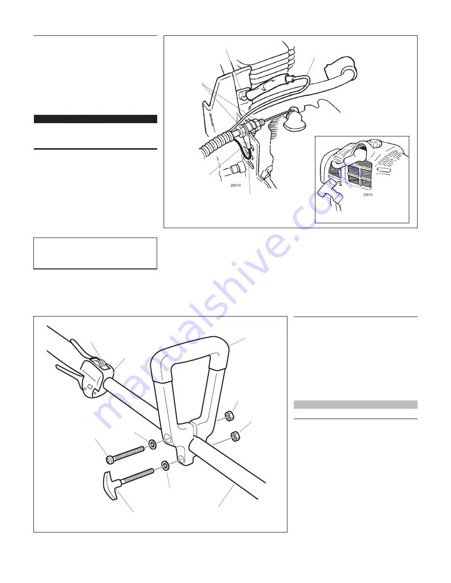
1.  Insert the throttle-cable housing into the 

notch on the fan cover, and clamp the 

ground wire terminal between the fan 

cover and the outer cable adjuster nut.              

See Figure 10.

2.  Tighten the two throttle cable adjuster 

nuts.

   IMPORTANT! 

Adjust and tighten the cable nuts to allow 

approximately 1/4-inch free play at the 

throttle trigger.

CAUTION! 

Routing of wiring must not interfere with 

throttle operation.

Figure 10

Reinstall the Spark 

Plug Cap

Black  Ignition 

Wire

Red Wire

Cable  Adjuster 

Nuts

3.  Using finger pressure only, connect 

the black ignition wire from the cable 

tube to the red ignition wire on the 

powerhead. Wire routing must be as 

shown in the illustration with the black 

wire located away from the throttle cable 

and carburetor linkage.

4.  Reinstall the engine cover and tighten 

the captive engine cover screw. 

5.  Reinstall the spark plug boot.

23028

Assembly

Handle

1.  Remove both screws from the handle.
2.  While spreading the handle at the 

mounting hole, position the handle on 

the outer tube as shown.

3.  Reinstall the two mounting screws in the 

handle, but do not tighten them at this 

time. 

NOTE:

The handle is recessed to receive the hex nuts.

4.  Locate the handle at the best position 

for operator comfort (usually about 10 

inches ahead of the throttle assembly).

5.  Secure the handle by tightening the 

mounting screw and the adjustment 

knob screw.

Handle

Hex Nut

Washer

Hex Nut

Outer Tube

Adjustment 

Knob

Mounting Screw

Washer

Connect the Handle to the  

Outer Tube.

Figure 11

Throttle  

Assembly

Ignition 

Switch

Summary of Contents for LE230

Page 1: ...NUAL LE230 EDGER Part Number 62714 94311 Rev 1 06 Minimize the risk of injury to yourself and others Read this manual and familiarize yourself with the contents Always wear eye and hearing protection...

Page 2: ...or attachments ALWAYS keep the unit as clean as practical Keep it free of loose vegeta tion mud etc ALWAYS hold the unit rmly with both hands when cutting or trimming and maintain control at all times...

Page 3: ...ammable material close to the engine muf er NEVER run the engine without the spark arrester screen in place The Properly Equipped Operator Always operate with both hands rmly gripping the unit Wear cl...

Page 4: ...ent Beware of a coasting blade when edging A coasting blade can injure while it continues to spin after the throttle trigger is released or after the engine is stopped Figure 2 50 FEET ALWAYS clear yo...

Page 5: ...leaner Type Non reversible ocked lter element Starting Method Recoil Stopping Method Slide switch Transmission Type Automatic centrifugal clutch w bevel gear EPA Emission Compliance Period Category A...

Page 6: ...s down Slide the outer tube into the powerhead until the throttle grip just contacts the tube clamp 6 Tighten the clamp screw rmly Figure 7 23013 Assembly Throttle Linkage and Ignition Leads Remove th...

Page 7: ...n wire on the powerhead Wire routing must be as shown in the illustration with the black wire located away from the throttle cable and carburetor linkage 4 Reinstall the engine cover and tighten the c...

Page 8: ...ne before refueling ALWAYS allow the engine to cool before refueling Wipe all spilled fuel and move the engine at least 10 feet 3 meters from the fueling point and source before restarting NEVER start...

Page 9: ...gine from the operat ing position WARNING The cutting attachment may rotate when the engine is started When the Engine Starts After the engine starts allow the engine to warm up at idle 2 or 3 minutes...

Page 10: ...s on your right hand side Begin each pass by positioning the unit over the work and with the engine run ning at about half throttle Slowly lower the blade to the ground while applying full throttle Gu...

Page 11: ...y maintenance repair or cleaning work on the unit make sure the engine and cutting attachment are completely stopped Disconnect the spark plug wire before performing service or maintenance work WARNIN...

Page 12: ...dusty or dirty conditions Remove the air cleaner element from the carburetor and clean it thoroughly with soap and water or compressed air let dry before reinstalling the element CAUTION Do not opera...

Page 13: ...pect the Gearcase Protector The metal gearcase protector P N 72958 16210 is installed to protect the gearcase ange from damage when working close to sidewalks or other abrasive surfaces and should be...

Page 14: ...epare it for storage Clean external parts thoroughly Drain all the fuel from the carburetor and the fuel tank IMPORTANT All stored fuels should be stabilized with a fuel stabilizer such as STA BIL To...

Page 15: ...g of the correct heat range For EMC compliance use NGK BMR6A Restart NO YES What To Check Possible Cause Remedy ENGINE DOES NOT START NO YES NO YES YES NO YES Is the engine overheating Engine is rough...

Page 16: ...et the switch and restart Refuel See page 8 Replace strainer Drain replace with clean fuel See page 8 Clean or replace spark plug with a Champion CJ8 or equivalent type spark plug of the correct heat...

Page 17: ...during a warranty repair altera tion accident failure to use the recommended fuel and oil or not performing required maintenance services b the replacement parts used for required maintenance service...

Page 18: ...18 NOTES...

Page 19: ...19 NOTES...

Page 20: ...hindaiwa com Shindaiwa Kogyo Co Ltd Head Of ce 6 2 11 Ozuka Nishi Asaminami Ku Hiroshima 731 3167 Japan Telephone 81 82 849 2220 Fax 81 82 849 2481 2006 Shindaiwa Inc Part Number 62714 94311 Revision...

Reviews:

Related manuals for LE230