background image


- 18 - 


<Caution> 


Never turn the starter switch to [START] position once the engine is running. 

 
6. Push back the choke. 

<Caution> 


Just after starting, the engine may stop if the choke is prematurely pushed back in. In 
this case, push back the choke slowly once the engine is warm. 

 
7. Keep engine idling for approximately 5 minutes. 


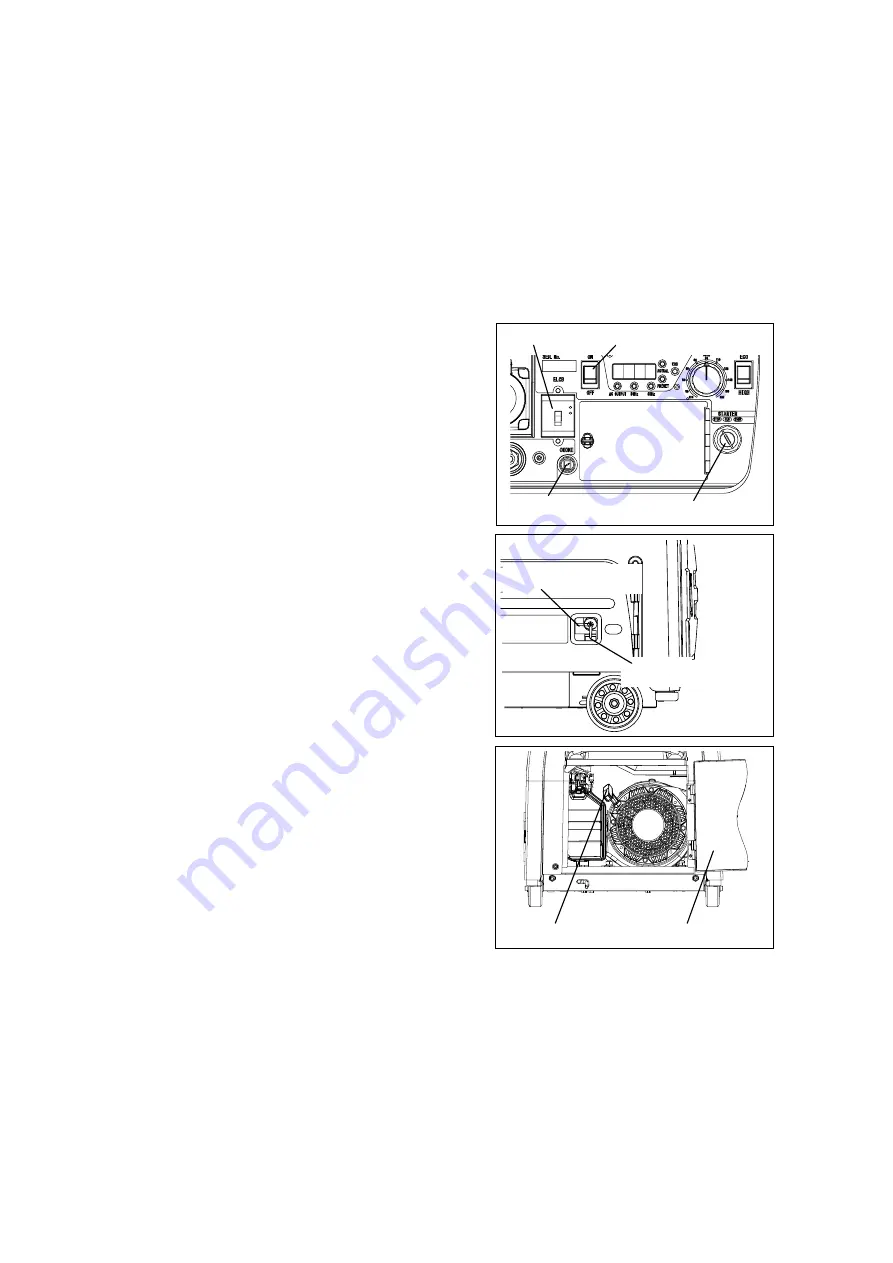
(2) Starting by Recoil Starter 

1. Switch the AC output switch to [OFF] position.   
2. Turn the fuel valve to [OPEN] position.   
3. Pull out the choke. 
4. Turn the starter switch to [RUN] position. 
5. Open the side door. 
6. Pull the recoil knob slowly to the compression 

point, then allow the recoil knob to return and 
pull it again to start. 

<Caution> 


Do not fully extend the recoil knob. 

 
7. After the engine starts, push back the choke. 

<Caution> 


Just after starting, the engine may stop if the 
choke is prematurely pushed back in. 
Therefore, push back the choke slowly along 
the engine condition and keep the choke back 
always when the engine is warm. 

 
8. Keep engine idling for approximately 5 minutes. 


[OPEN] 

Fuel Valve [CLOSE] 

Recoil Knob 

Side Door 

Starter Switch 

ELCB 

Choke 

AC Output Switch 

Summary of Contents for EGW165M-I/UKV

Page 1: ...R S AND OPERATOR S MANUAL Air Cooled 4 Cycle OHV Engine EGW165M I UKV X750 031 03 2 X750804 430 2 CAUTION Do not operate the Generator Welder or any other appliance before you have read and understood...

Page 2: ......

Page 3: ...t Please store this manual with the equipment for easy reference The following convention will be used throughout the manual to indicate the degree of caution Warning Can cause serious injuries or dea...

Page 4: ...g statement refers to the noise level data contained in the EC Declaration of Conformity contained on the next page of this manual The figures quoted are emission levels and are not necessarily safe w...

Page 5: ...ion EU 2019 1784 as its implementing measure the requirements of Directive 2011 65 EU use of harmonized standard EN IEC 63000 2018 the requirements of Directive 2000 14 EC Noise measurements have been...

Page 6: ...s 9 5 7 Oil Sensor 10 5 8 Display 10 5 9 Wheel Brake 11 5 10 Earth Leakage Circuit Breaker and Grounding 12 6 Operation 13 6 1 Initialization Pre check 13 6 2 Starting 17 6 3 Stopping 19 7 Welding Ope...

Page 7: ...check or maintenance must always keep the key Warning Electromagnetic Interference Persons using a heart pacemaker are not allowed near the Generator work area while the Generator is in operation wit...

Page 8: ...e items away from the welding area as welding creates hot sparks Always set up extinguishers near the welding area Always drain fuel before transporting by vehicle Do not operate the equipment when it...

Page 9: ...levels When checking engine oil or changing oil always stop the engine and wait until the engine cools down Do not open the oil gauge oil filler cap during operation as hot oil may cause injury Be sur...

Page 10: ...as specified in the following figure When ordering the label use the following part numbers 1 Suffocation from Exhaust Fumes X505 011481 2 Electric Shock X505 011470 3 Hot Surface X505 011490 4 High...

Page 11: ...0 Rated Output kVA 3 2 Rated Current A 29 Power Factor 1 0 Rating Continuous Engine Model Yamaha MZ300 Type Air cooled 4 Cycle OHV Gasoline Displacement L 0 296 Rated Output kW min 1 5 8 3600 Fuel Unl...

Page 12: ...butor when utilizing this equipment around devices with microcomputer control or ultra precision items which are very sensitive to voltage fluctuation Keep the equipment away from those devices to avo...

Page 13: ...Battery 14 Earth Grounding Terminal 15 Plug Cap Spark Plug 16 Fuel Valve 17 Air Cleaner Cleaner Cover 18 Recoil Knob 19 Fuel Inlet 20 Front Door 21 Side Door 22 Plug Maintenance Cover 23 Handle 24 Lif...

Page 14: ...60 Hz 5 3 Engine Speed Control Switch Eco mode The Eco mode is designed to control the engine speed based on the required current to minimize the noise level and fuel consumption Turn the Idle contro...

Page 15: ...the stable arc reduces the amount of spatter 5 5 AC Output Switch This AC Output Switch changes between connecting and disconnecting of AC power source This switch does not have function to automatic...

Page 16: ...gradation of engine oil Please check the engine oil periodically and change if required Refer to 9 Checking and Maintenance 1 Change Engine Oil P 25 Always operate the equipment on a flat and stable s...

Page 17: ...d when the AC output switch is OFF the AC output lamp will turn off 7 Frequency The lamp turns RED in accordance with the position of the Frequency Switch 8 Eco mode When the engine speed control swit...

Page 18: ...to ON position 4 Press the test button Gray in the ELCB Once the test button is pressed the ELCB indicator White must be out and the switch in the middle position 5 Push down the ELCB switch OFF posit...

Page 19: ...ing Engine Oil Position the equipment on a flat and stable surface Open the oil maintenance cover and insert the oil gauge into oil inlet to check the engine oil level do not screw the oil gauge into...

Page 20: ...failure Engine Oil Selection Use the engine oil with the correct viscosity based on the ambient temperature Refer to the chart below Caution Use oil of Class SE or superior Check the remaining oil lev...

Page 21: ...ose connection When checking for any fuel leaks OPEN the fuel valve Be sure to CLOSE the fuel valve after checking Level Mark Fuel Strainer Net Warning Fire When checking and refueling fuel always sto...

Page 22: ...terminal Caution Only use the following battery Yuasa YTX9 BS It is unnecessary to check the fluid level and refill the distilled water as this equipment is installed with a 12 V sealed battery only...

Page 23: ...seconds or more 5 When the engine starts release the starter key immediately Warning Suffocation from exhaust fume Exhaust fumes from the engine contain many elements harmful to humans Do not operate...

Page 24: ...out the choke 4 Turn the starter switch to RUN position 5 Open the side door 6 Pull the recoil knob slowly to the compression point then allow the recoil knob to return and pull it again to start Cau...

Page 25: ...ing cables should be used uncoiled When the welding cables are used coiled welding capacity is reduced Correct Size of Cable Unit mm2 20 m 30 m 40 m 60 m 80 m 100 m 165 A 22 22 30 50 60 80 145 A 22 22...

Page 26: ...s a consequence 7 4 Duty Cycle Duty cycle means the welding time ratio for 10 minutes The duty cycle of the equipment is 50 namely the welding time is 5 minutes or less for each continuous 10 minutes...

Page 27: ...of radio and television broadcasts Warning Suffocation from welding fumes Be sure to wear a fume proof mask during operation as welding fumes contain poisonous gases and dust Pay attention to the airf...

Page 28: ...tilizing this equipment around devices with the microcomputer control or the ultra precision items which are very sensitive to voltage fluctuation Keep the equipment away from those devices to avoid i...

Page 29: ...udged only by the rated output or the power consumption due to the efficiency and character of the components Applicable Load For reference only Load Capacity Watt Electric Bulb Heater etc 3200 Electr...

Page 30: ...ater source No Checking Item Startup Every 50 hrs Every 100 hrs Every 300 hrs Every 500 hrs Other 1 Check Supply Engine Oil P 13 2 Check Leakage Fuel Engine Oil P 15 3 Check Battery Terminal Tightenin...

Page 31: ...leakage from the oil drain outlet after changing oil 2 Clean Adjust Spark Plug Clean Adjust Every 50 hours 1 Open the plug maintenance cover 2 Remove the plug cap and remove the spark plug 3 If the sp...

Page 32: ...ition 3 Unscrew the bolts 4 Pull out the fuel valve 5 Remove the strainer cup by turning the ring counter clockwise 6 Discard any dust or water inside the strainer cup and clean away dust from the net...

Page 33: ...ge is necessary Holder Exhaust Wire Mesh Fuel Valve Net Seal Strainer Cup Ring Warning Explosion The battery may emit some combustible gas Keep it away from fire and sparks A loose battery terminal ca...

Page 34: ...citors and batteries handle the waste parts thereof carefully so that they do not leak due to cracking If the equipment is not to be used for more than 2 months perform the following maintenance and s...

Page 35: ...nd Maintenance 3 Clean and Change Air Cleaner P 26 14 Remove the battery Refer to 9 Checking and Maintenance 6 Checking the Battery P 27 Always remove negative side first and always reinstall positive...

Page 36: ...1 Wrong setting of current adjustment dial 2 Poor contacts of cables 3 Improper cable diameter 4 Improper connection to the base material 5 Engine output is down 1 Turn the dial CLOCKWISE 2 Contact ca...

Page 37: ...31 12 Wiring Diagram...

Page 38: ......

Page 39: ......

Page 40: ...1 7 2 SUEHIROCHO OHME TOKYO 198 8760 JAPAN PHONE 81 428 32 6118 FAX 81 428 32 6145 2020 Printed in Japan...

Reviews: