


3-2
109823 2/09
3.
Check the valve cap-contact surface for uneven
wear and streaks. If wear is insignificant, grind flat
with oilstone or grinder, otherwise, replace.
Cylinder head assembly
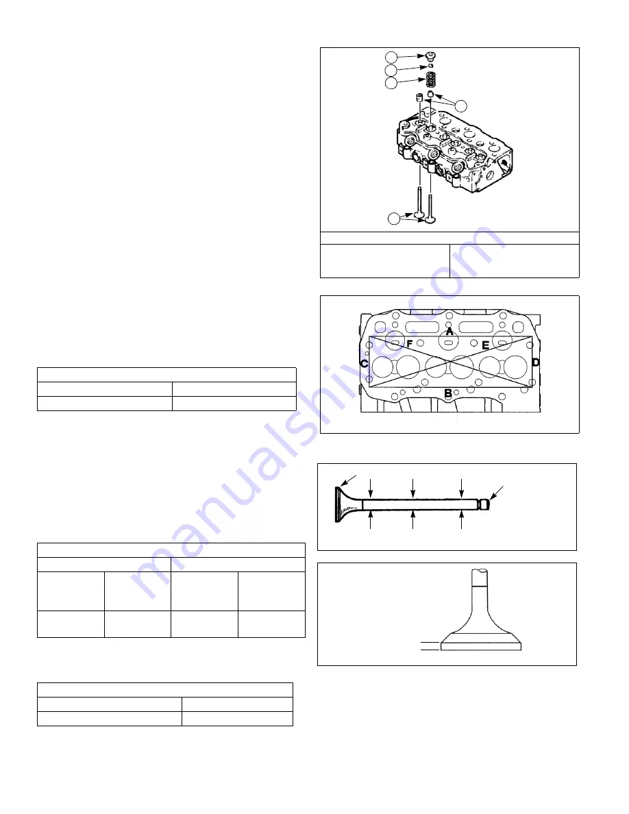
Disassembly
1.
Using a valve spring compressor, compress the
valve spring to remove the valve cotter, retainer,
spring and valve.
2.
Remove the valve guide seal.
Inspection and service
1.
Check for distortion of cylinder head bottom surface
by using a straight edge. Using Fig. 3-5 as a guide,
and a feeler gage, check for distortion at the six
positions—A through F. If distortion exceeds the
repair value, correct using a surface grinder.
2.
Valve guide and valve stem
a.
Check the head and stem of each valve and
replace if burned, worn, or deformation is
excessive.
b.
Measure the outside diameter at positions I, II, and
III on the valve stem with a micrometer and
replace if less than the service limit.
c.
Replace a valve if its head thickness is less than
service limit.
Distortion at cylinder head bottom surface in(mm)
Standard assembling value
Repair value
Less than 0.0020(0.05)
More than 0.0047(0.12)
Wear of valve stem ø in(mm)
Intake valve
Exhaust valve
Standard
assembling
value
Service limit
Standard
assembling
value
Service limit
0.274-0.2744
(6.955–6.97)
Less than
0.2712(6.89)
0.273-0.274
(6.94–6.955)
Less than
0.269(6.84)
Valve head thickness in(mm)
Standard assembling value
Service limit
0.0305-0.0423(0.775–1.075)
Less than 0.0197(0.5)
Fig. 3-4
1. Valve guide seal
2. Spring
3. Retainer
4. Valve
5. Valve cotter
1
2
5
3
4
Fig. 3-5
Fig. 3-6
Fig. 3-7
I
II
III
Stem End
Head End
Thickness
Summary of Contents for N843
Page 8: ...1 4 109823 2 09...
Page 11: ...109823 2 09 2 3 Engine Sectional Drawing...
Page 18: ...2 10 109823 2 09...
Page 46: ...109823 2 09 4 16...
Page 66: ...5 20 109823_2 09...