background image

SYNC

POWER

ON/OFF

L/R

L/R

POWER

MOTOR

SYNC

1

3

2

14/15

13/15

SYNC

POWER

ON/OFF

L/R

L/R

POWER

MOTOR

SYNC

1

2

3

4

Upper Beam

Middle Beam

Lower Beam

Block upper beam temperately 
when adjusting lower beam

Block lower beam temperately 
when adjusting upper beam

Upper Beam Adjustment Screw

Lower Beam Adjustment Screw

Remove screen protector 

before adjustment

Adjust up/down 

position of 

upper beam

Adjust left/right 

position of 

upper beam

Adjust up/down 

position of 

lower beam 

Adjust left/right 

position of 

lower beam

Adjust upper beam 

position to align the cross 

calibration pattern

Adjust lower beam 

position to align the cross 

calibration pattern

Adjust the middle beam 

image to align with upper 

and lower beam image

Seal the adjustment 
holes with adhesive 

tape after installation

Adjusting middle beam 

image size in left and 

right simultaneously.

Middle Beam 

Adjustment Screw

Middle Beam 

Adjustment Screw

9. Image Adjustment

Clear  3D  imagery  synthesis  depends  on  the  upper  and  lower  beam  image 
position and the middle beam image size.

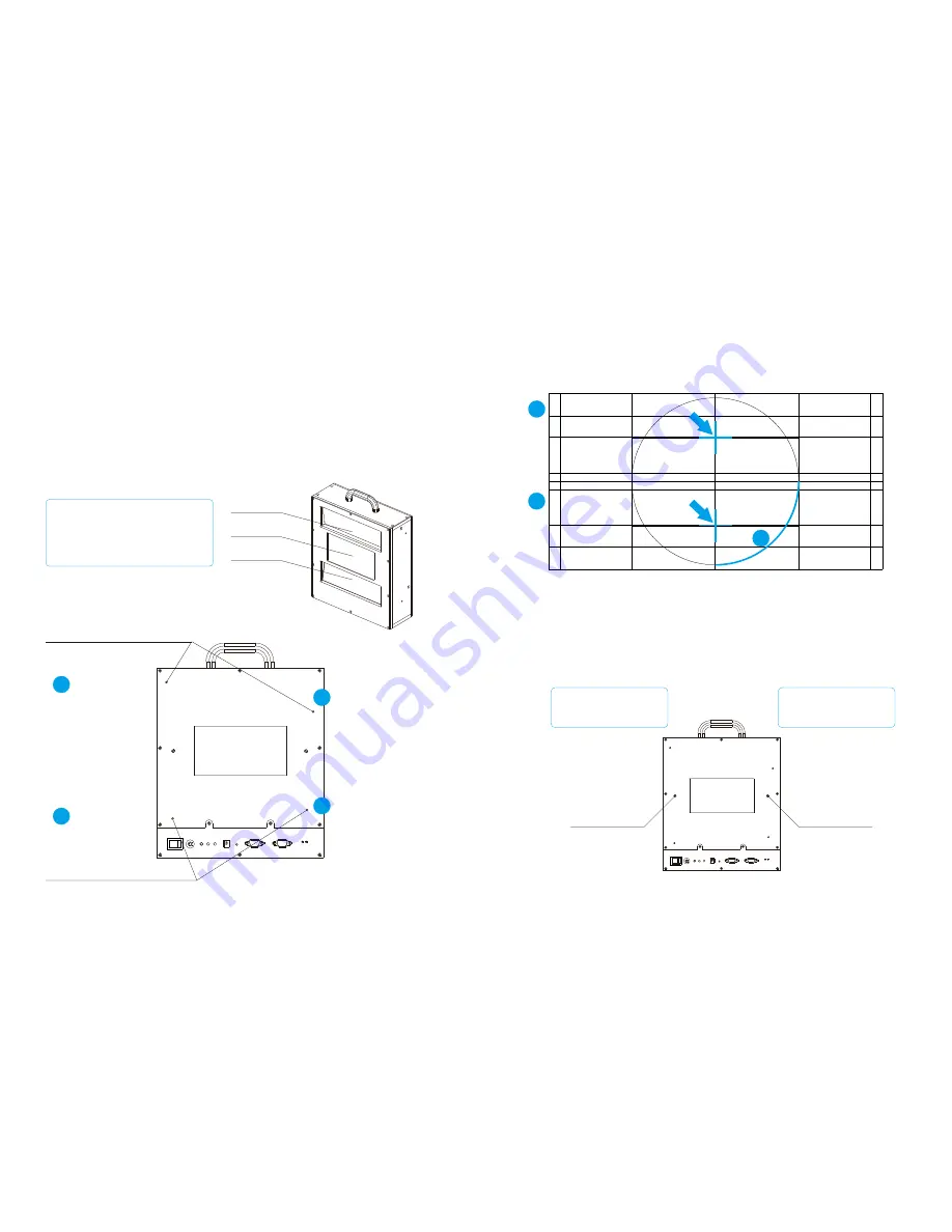
9.1  Fitting  the  Upper  and  Lower  Beam  Position 
Adjustment


Adjustment  screws  are  located  on  the  back  of  optical  unit.  Use  left 
adjustment  screw  to  adjust  up/down  position  of  upper  and  lower  beam. 
Use right adjustment screw to adjust left/right position of upper and lower 
beam, as shown in 

Figure 9-1-1.

Figure 9-1-1 Fold Mirror Adjustment

Position projector lens focuses on the screen, fine adjust upper beam and 
lower  beam  position  to  coincide  the  cross  calibration  pattern  align  with 
middle beam, when finish, adjust the size of middle beam image to center 
align the whole page, as shown in 

Figure 9-1-2.

Figure 9-1-2 Apply the Correction by Adjusting the Fold Mirror

9.2 Adjust Middle Beam Image Size

The  middle  beam  image  size  adjustment  screws  are  located  on  both  sides 
of  the  light  incidence  window.  Adjust  middle  beam  image  to  align  with 
upper and lower beam image, as shown in 

Figure 9-2.

Figure 9.2 Holes for Adjusting Middle Beam Image Size

Summary of Contents for FDT05

Page 1: ...el No FDT05 User Manual SHENZHEN HONY OPTICAL CO LTD Address 4th Floor Jinlaiwang Science Park No 7 Jiayi Industril Zoon Guiyue Road Guihuacun Guanlan town Baoan District Shenzhen Tel 86 755 29045554 Fax 86 755 29045524 Website www hony3d com ...

Page 2: ...alling Pedestal Mount Components 6 6 2 Installing the Motorized Bracket 7 6 3 Installing Lifting Mechanism and Optical Unit 8 7 System Connection 9 7 1 Device Interface 9 7 2 LED Status Indicators 10 8 Adjustment 11 8 1 Centering Adjustment 11 8 2 Height and Angle Fine Adjustment 12 9 Image Adjustment 13 9 1 Fitting the Upper and Lower Beam Image 13 9 2 Fitting the Middle Beam Image Size 14 10 Cau...

Page 3: ...smooth motion and vivid picture quality to the cinema audience Cost Saving With Turbo Screen system cinemas can use lower brightness projector bulbs for projection without sacrificing brightness which reduces operating costs More compatible Turbo Screen system is suitable for projection hall with minimum projection distance of 11 meters and supports 1 1 2 minimum throw ratio Meanwhile it reduced t...

Page 4: ... SYNC Cable Motor Driving Signal Cable Figure 5 1 System Components System size 800 350 1050mm total weight is about 32KG System is composed of valuable optical elements Please handle with care to avoid damage 5 1 Optical Unit Figure 5 1 1 Optical Unit Optical Unit is composed of valuable optical elements Dimensions 282 96 360mm weight about 10KG It is an important part of Turbo Screen system that...

Page 5: ... with the projector pedestal It can be used to adjust the Turbo Screen system s height angle left and right as well as front and rear position to perfectly fit the space of the system and projector It receives signal from projector Turbo Screen through Signal SYNC Cable and identify the projector status of 2D or 3D and move to the right position Figure 5 2 Bracket 6 System Installation 6 1 Install...

Page 6: ... please install it on the other side which far away from projector lens 6 2 Installing the Motorized Bracket Fix aluminum section 30 60 800mm onto the pedestal mount components with L shape block and then install the motorized bracket onto the aluminum section as shown in Figure 6 2 Figure 6 2 Installing the Motorized Bracket 6 3 Installing Lifting Mechanism and Optical Unit Fix lifting mechanism ...

Page 7: ...t POWER interface Power Adapter 24V 3 75A input Figure 7 1 Device Interface 7 2 LED Status Indicators After the connection is completed turn on the system and digital projector to play a 3D movie check the cables are connected correctly by observing the LED status indicators on the front panel as shown in Figure 7 2 Figure 7 2 LED Status Indicators POWER Indicator Power on optical unit If the POWE...

Page 8: ...for play 3D movie The optical unit position for play 2D movie 8 Adjustment 8 1 Centering Adjustment Power on optical unit and the projector to play 3D movie the optical unit will move automatically to the side which close to the lens of projector Fine adjust optical unit position to align light incidence window right in front of projector lens as shown in Figure 8 1 Figure 8 1 Centering Adjustment...

Page 9: ...m Adjustment Screw 9 Image Adjustment Clear 3D imagery synthesis depends on the upper and lower beam image position and the middle beam image size 9 1 Fitting the Upper and Lower Beam Position Adjustment Adjustment screws are located on the back of optical unit Use left adjustment screw to adjust up down position of upper and lower beam Use right adjustment screw to adjust left right position of u...

Page 10: ...he like internal optical components may be contaminated System is composed of precision optics with invisible coating on the surface use micro fiber dust free cloth and electronic grade ethanol to clean the light incidence window and light exit window Check the light incidence window and light exit window with bright light to make sure all stain are gone Please turn off the power when system is no...

Reviews: