background image

Page 2

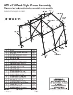
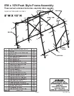
8'W x 8'H Peak Style Frame Assembly

Please read and understand instructions completely before assembly.

Layout out frame parts as shown.

ATTENTION:

FOR MISSING OR

REPLACEMENT PARTS

OR QUESTIONS, PLEASE 

CONTACT

CUSTOMER SERVICE:

1.800.524.9970

CANADA 1.800.559.6175

end rib

CrOSS

 rail

tOP rail

middle ribS

end rib

wind 

braCe

COver rail

8' W X 8' H

item nO.

deSCriPtiOn

Part nO.

1

2

3

4

5

6

7

8

9

10

11

12

13

14

15

16

17

18

19

20

21

22

23

Swed.UPriGHt tUbe 67 3/4"X1-5/8"d. 1 end

tOP bend tUbe 15"X1-5/8" dia.

Side bend tUbe 15"X1-5/8" dia.

raFter PiPe, 42X1190Xt1,4 SwG bOtH endS Gry

COrner UPriGHt tUbe 57 3/4"X1-5/8" dia.

bend COrner leG 21"X1-5/8" dia.

CrOSS rail 48-1/2"X1.163",Plain endS 2 H

CrOSS rail 50-1/2"X1.163", 1 SwdG 2 HOle

CrOSS rail Plain end 47"X1-1/8" dia.

CrOSS rail Plain endS 45 3/4"l, 2 HOleS

CrOSS rail SwedGed 48 7/8"X1-1/8" dia.

baSe FOOt, 1-3/8 Steel, Gry

3-way tOP COnneCtOr

3-way COver rail ClamP 1 5/8" PiPe

4-way COver rail ClamP

wind braCe Flat endS 62-3/4"X1-1/8"dia.

SHelterlOCK anti-raCK deviCe 42X28mm

bOlt, CarriaGe,1/4"X1-5/8"

bOlt, CarriaGe 1/4"x2"

bOlt, CarriaGe 1/4" X 3"

bOlt, ladder rd,F/tOPCreStS,1/4"X3 1/2"l

nUt, HeX, 1/4-20

anCHOr, aUGer 3"X15"  witH Cable & ClamP

10126

10131

10132

10127

10128

02031

02030

10134

10110

10133

10113

10121

10112

10111

10135

800260

10115

10114

00670

00669

01010

00847

bOlt CaPS

24

10150

6

24

5

24

7

13

19

1

12

24

24

16

11

4

18

21/22

8

21/22

3

3

19

24

23

23

24

21/22

13

9

2

5

24

20

5

1

7

8

20

20

6

14

10

10

10

15

14

12

6

5

24

24

16

3

17

17

3

19

19

4

4

05-10DT13-0A

800465

Summary of Contents for Peak Style 8' W x 8' H

Page 1: ...uctions 8 W x 8 H or 10 H Peak Style Frame Assembly Before you start 2 individuals recommended for assembly approximate time 3 hours Recommended tools Power Drill Safety Glasses Rope Tape Measure Ratc...

Page 2: ...48 1 2 X1 163 Plain endS 2 H CrOSS rail 50 1 2 X1 163 1 SwdG 2 HOle CrOSS rail Plain end 47 X1 1 8 dia CrOSS rail Plain endS 45 3 4 l 2 HOleS CrOSS rail SwedGed 48 7 8 X1 1 8 dia baSe FOOt 1 3 8 Stee...

Page 3: ...OSS rail 50 1 2 X1 163 1 SwdG 2 HOle CrOSS rail Plain end 47 X1 1 8 dia CrOSS rail Plain endS 45 3 4 l 2 HOleS CrOSS rail SwedGed 48 7 8 X1 1 8 dia baSe FOOt 1 3 8 Steel Gry 3 way tOP COnneCtOr 3 way...

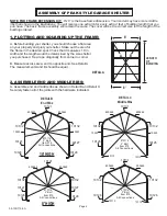
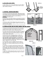
Page 4: ...termined by the size shelter you purchased Tie a rope diagonally from corner to corner B Measure across area end to opposite end See Detail A The measurement A and B should be equal 8 8 A B LENGTH OF...

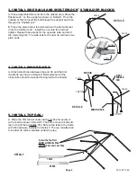
Page 5: ...n ends 4 Install Wind Braces A Attach wind brace between the end rib and the first middle rib as shown in Detail E Bolts attached at the cross rails should be inserted facing inside the shelter 5 Inst...

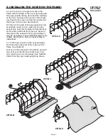
Page 6: ...from the top bend and place the webbing in between The top rail should pass through the loop of the webbing Reconnect top rail onto rib and secure it with the screws indicated See Detail I C Remove t...

Page 7: ...pocket slot at the first middle rib from the front and the first middle rib from the rear Some of the pipe will be exposed For long buildings it may be necessary to use additional pipes in the middle...

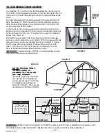
Page 8: ...3 way and 4 way clamps as shown in Detail P Check that the rails are evenly spaced 8 above the ground on both sides Push down on the cover rails and connectors one at a time to tighten the bolted clam...

Reviews: