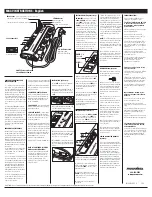
4-l. Remove the two screws off the intake duct assembly. Detach the intake duct assembly from the bottom
cabinet.
4-2. Remove the five screws off the optics mechanism assembly. Detach the assembly from the bottom cabinet.
Remove the two lock screws off the lamp/cage
module unit.
Remove the three countersunk lock screws off
the upper and lower lamp cases.
5-3. Remove the lock screw and the nut off the
lamp terminal.
5-4. Release the lamp lock spring off the hook
below the lower lamp case. Take out the lamp/
mirror assembly.
Lamp/cage module unit
5-3
5-2
Optics
Ass’y
Summary of Contents for XV-C1E
Page 24: ...XV Cl E II Block diagram 24 ...
Page 34: ...XV Cl E 77 VJ PWMl NC 78 m PWM2 P CON 1 0 P CON 1 79 NC NC 80 P63 PWM3 NC 34 ...
Page 35: ...4 LCD Panel RLCDP0037CEZZ I Pins XV Cl E 35 ...
Page 45: ...XV Cl E OUNTK9348DEo fO5 06 mm11 I I ...
Page 49: ...XV Cl E I 7 I 8 I 9 I 10 I 11 I 12 ...
Page 77: ...XV ClE 1 IECHANISCHE BAUTEILE I 7 I 8 I 9 I 10 I 11 I 12 J 114 ...
Page 82: ...S H A R P TQ0240 S Printed in Japan In Japan gedruckt MW KD ...


