background image

XE-A203U/XE-A203A

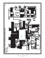
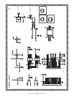
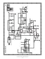
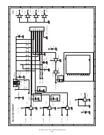
CIRCUIT DIAGRAM AND PWB LAYOUT

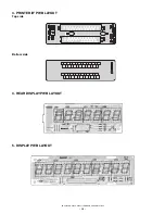
– 26 –

Bot

tom side

Summary of Contents for XE-A203 - Cash Register Thermal Printing Graphic Logo Creation

Page 1: ...ON This document has been published to be used for after sales service only The contents are subject to change without notice LEAD FREE SOLDER MODEL XEA203USME ELECTRONIC CASH REGISTER MODEL XE A203 U and A version LEAD FREE SOLDER CHAPTER 1 SPECIFICATIONS 1 CHAPTER 2 OPTIONS 5 CHAPTER 3 MASTER RESET AND PROGRAM RESET 6 CHAPTER 4 HARDWARE DESCRIPTION 6 CHAPTER 5 TEST FUNCTION 12 CHAPTER 6 CIRCUIT ...

Page 2: ...ity is inferior to conventional one it is apt to keep the soldering iron in contact with the PWB for longer time This may cause land separation or may exceed the heat resistive tem perature of components Use enough care to separate the soldering iron from the PWB when completion of soldering is confirmed Since lead free solder includes a greater quantity of tin the iron tip may corrode easily Turn...

Page 3: ...de switch Power cord Take up spool Print roller release lever Print roller arm Inner cover Paper roll cradle Paper positioning guides 1 2 3 4 5 6 7 8 9 CL 00 0 DEPT SHIFT CLK CONV 1 RA VOID RFND 2 NUMBER SHIFT SPACE DC ESC BS RCPT PO FOR PLU SUB DEPT B A 20 4 C 19 3 D 18 2 E 17 1 G F 24 8 H 23 7 I 22 6 J 21 5 L K 28 12 M 27 11 N 26 10 O 25 9 Q 32 P 16 R 31 15 S 30 14 T 29 13 AUTO TAX TAX2 SHIFT TA...

Page 4: ...n you have registered ten times the display will show 0 2 3 3 9 3 0 3 1 3 2 Receipt function status The indicator _ appears in the RCPT OFF position when the receipt function is in the OFF status Time Appears in the far right six positions hour minute or hour minute in the OP X Z REG or MGR mode is displayed in the morning AM and in the afternoon PM In the REG or MGR mode press the TM SBTL key to ...

Page 5: ... code PGM Mode 10 P CASH CHECK CHARGE 10 F Light up when a registration is finalized by depressing CASH CHECK CHARGE key SUB TOTAL short tender 10 o Change 10 C Light up whenever the change due amount appears in the display Currency Conversion 10 c Light up whenever the foreign amount appears in the display Department 9 10 No zero suppressed PLU 7 10 No zero suppressed Repeat 8 Endless count start...

Page 6: ...ollowing method with 2 days 1 Power on the ECR 2 Mode switch turn to REG mode 3 Release the OLD dry batteries 3 pieces 4 Insert the NEW dry batteries 3 pieces 5 Confirm the low battery symbol L lights off 2 LOW BATTERY Low battery indication will appear on the left side of display when the battery voltage is low Type SEC SECL Model name of the drawer box SJ415 SJ423 Size mm 330 W x 418 D x 98 H 35...

Page 7: ...attached to it the master reset operation is automatically performed after the power has been restored 0 00 Battery is OK L 0 00 Low battery You have to change the batteries L 0 00 No battery You have to change the batteries immediately F 12 34 Battery is OK L 12 34 Low battery L indicate instead of F L 12 34 No battery L indicate instead of F Note NO BATTERY When the NO BATTERY is display the mas...

Page 8: ...WER LV125 HCT04 SD CARD USB Type B MOTOR PRINTER MT53II Driver Sensor KEY RETURN KEY SCAN KEY SWITCH Decoder 74HC138 x 2 4 to 16 LED Front 10 PopUp 7 DIG Driver SEG Driver 74H374 USB Controller M66291GP S RAM 128KByte CPU Renesus M30624MWP D85FP ROM 320KByte RAM 24KByte CPU internal RAM 24KByte 00400h 063FFh External RAM 128KByte 08000h 27000h Area that can be used 124KByte 00000h 00400h 063FFh CP...

Page 9: ... P25 67 A5 A5 O H Out L ADDRESS BUS A5 P26 66 A6 A6 O H Out L ADDRESS BUS A6 P27 65 A7 A7 O H Out L ADDRESS BUS A7 P30 63 A8 A8 O H Out L ADDRESS BUS A8 P31 61 A9 A9 O H Out L ADDRESS BUS A9 P32 60 A10 A10 O H Out L ADDRESS BUS A10 P33 59 A11 A11 O H Out L ADDRESS BUS A11 P34 58 A12 A12 O H Out L ADDRESS BUS A12 P35 57 A13 A13 O H Out L ADDRESS BUS A13 P36 56 A14 A14 O H Out L ADDRESS BUS A14 P37 ...

Page 10: ... I In KEY IN P91 6 P91 P91 I In KEY IN P92 5 P92 P92 I In KEY IN P93 4 P93 P93 I In KEY IN P94 3 P94 P94 I In KEY IN P95 2 P95 P95 I In KEY IN P96 1 P96 P96 I In KEY IN P97 100 P97 P97 I In KEY IN P100 97 AN0 P100 I In HEAD TEMPERATURE MONITOR P101 95 AN1 P101 I In HEAD VOLTAGE MONITOR P102 94 P102 STB2 O H In PRINTER STB2 P103 93 AN3 VBAT I In BATTERY VOLTAGE P104 92 P104 NU O L Out L UNUSED P105...

Page 11: ... card chip select signal 34 P64 CLKS1 SD_POW SD card power on signal 35 P63 TXD0 SD_TXD TxD signal 36 P62 RXD0 SD_RXD RxD signal 37 P61 CLK0 SD_CLK Serial CLK signal Pin No CPU PORT Use signal Function 76 P14 IN2 Paper feed motor IN2 75 P15 IN1 Paper feed motor IN1 74 P16 ENA2 Paper feed motor ENA2 73 P17 ENA1 Paper feed motor ENA1 1 2 27 1 5k 27 3 4 1 0uF CPU A0 A1 A6 D0 D7 CS1 RD WR RESUSB DREQU...

Page 12: ...138 from KST0 KST3 signals OTHERS CPU PORT 9 POWER 10 DRAWER The XE A203U A203A is provided with 1CH of a drawer port The drawer solenoid drive time is as follow 55ms max 50ms min Head temperature A D conversion value DEC Operation Less than 10 C 929 1023 Motor lock 10 C Less than 0 C 869 928 Print in the conduction time at 0 C 0 C Less than 70 C 232 868 Print in the conduction time speci fied on ...

Page 13: ...to a position other than the SRV mode The printer prints as follows 3 PRINTER TEST 1 Key operation 2 Test procedure 3 lines of 24 Z s are printed 3 Display 4 End of testing The test will automatically be terminated after the printer prints NO Code Description 1 100 DISPLAY BUZZER TEST 2 101 KEY CODE 3 102 PRINTER TEST 4 104 KEYBOARD TEST 5 105 MODE SWITCH TEST 6 106 PRINTER SENSOR TEST 7 107 CLOCK...

Page 14: ... paper end sensor and head up sensor 3 Display X Paper end sensar 1 Paper present 0 Out of paper Y Head up sensor 1 Head down 0 Head up 4 End of testing You can exit the test mode by pressing any key and the printer prints the following 7 CLOCK DISPLAY TEST 1 Key operation 2 Test procedure The clock is displayed 3 Display 4 Check that A Check blinks at an interval of 500ms B Check the clock counts...

Page 15: ...er this test RAM 00400H 053FFH area is tested in the following procedure a Data in the test area is stored b Write 00H c Read and compare 00H and then write 55H d Read and compare 55H and then read AAH e Read and compare AAH f Stored data is restored 3 Display 4 End of testing The test will automatically be terminated and the printer prints as follows x 1 Data error x 2 Address error When an error...

Page 16: ...ill automatically be terminated and the printer prints as follows 16 SD CARD TEST SD CARD INFORMATION 1 Key operation 2 Test procedure The SD card is detected and the write protect status is displayed After completion of the test the SD card register value is printed Error print list 3 Display 4 End of the test When any key is pressed the SD card register is read and the end print is made RCPT PO ...

Page 17: ...53 52 51 50 49 48 47 46 45 44 43 42 41 40 39 38 37 36 35 34 33 32 31 D7 D8 D6 D5 D4 D3 D2 D1 D0 AN7 AN6 AN5 AN4 AN3 AN2 AN1 AVSS AN0 VREF AVCC SIN4 SOUT4 CLK4 TB4IN TB3IN SOUT3 SIN3 CLK3 BYTE CNVSS XCIN XCOUT RESET XOUT VSS XIN VCC NMI INT2 INT1 INT0 TA4IN U TA4OUT U TB3IN TBEOUT TA2INW TA2OUTW TA1IN V TA1OUT V TB5IN TB5OUT D9 D10 D11 D12 D13 D14 D15 A0 A1 A2 A3 A4 A5 A6 A7 VSS A8 VCC A9 A10 A11 A...

Page 18: ...8 4 D18 1N4002 1 2 C35 10uF 50V IC11 LB1838M 1 2 13 6 9 7 14 4 11 3 5 12 10 8 VCC ENA1 ENA2 IN1 IN2 GND GND VS1 VS2 OUT1 OUT2 OUT3 OUT4 VCONT R73 30KF D4 1SS133 1 2 C41 0 1uF R11 10K F1 T500mA 250V TP2 IC10 74HC138 1 2 3 4 5 6 7 8 9 10 11 12 13 14 15 16 A B C G2A G2B G1 Y7 GND Y6 Y5 Y4 Y3 Y2 Y1 Y0 VCC C28 0 1uF C36 0 1uF Q4 2SD2212 1 3 2 CN6 1 25 2 34P 1 2 3 4 5 6 7 8 9 10 11 12 13 14 15 16 17 18 ...

Page 19: ...15 RB060L40 1 2 D17 1SS133 1 2 D6 FMB G24H 1 2 R7 10K F3 1 0A R105 560 R83 17 8KF Q8 KRC106S 2 1 3 R101 3 9KF D13 RB721Q 1 2 R96 910F R92 2 7KF R93 2 7K Q7 KRA106S 2 1 3 CN7 VH 2A 1 2 R86 18K L2 180uH C47 220uF 50V 1 2 D12 1N4002 1 2 R82 10 FUSE R85 3 3KF ZD5 UDZS4 3B 1 2 ZD1 PTZ9 1B 1 2 L1 63uH R89 2 2K D9 RB060L40 1 2 ZD4 UDZS5 1B 1 2 IC14A BA10393 3 2 1 8 4 IC13 PQ1CG2032FZ 1 4 2 5 3 VIN ADJ VO...

Page 20: ...14 7 R112 10K C57 1uF C61 0 1uF IC17B 74LV125 5 6 14 4 7 R119 33 R104 100K C60 100pF R117 100K C62 100pF C66 100uF 50V 1 2 IC17A 74LV125 2 3 14 1 7 IC16B 74HCT04 3 4 14 7 R109 10K C64 1000pF C59 100pF R113 100K IC17C 74LV125 9 8 14 10 7 IC16E 74HCT04 11 10 14 7 IC16F 74HCT04 13 12 14 7 R116 100K C65 1000pF R110 51 R118 33 C58 100pF IC17D 74LV125 12 11 14 13 7 R114 100K CN9 ALPS SCDA2A0300 1 2 3 4 ...

Page 21: ...133 1 2 R142 120 Q18 1 3 2 Q12 1 3 2 4 7K C73 100pF CN12 52045 3445 1 2 3 4 5 6 7 8 9 10 11 12 13 14 15 16 17 18 19 20 21 22 23 24 25 26 27 28 29 30 31 32 33 34 R144 120 R126 47K R127 47K R121 47K Q24 3 1 2 R131 12K 2 7K Q30 3 1 2 R132 12K R140 120 7 2K D21 1SS133 1 2 Q11 1 3 2 D22 1SS133 1 2 CN15 52045 0745 1 2 3 4 5 6 7 3K Q15 1 3 2 Q17 1 3 2 R128 47K D27 1SS133 1 2 D20 1SS133 1 2 Q21 3 1 2 C71 ...

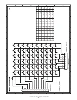
Page 22: ...P92 P97 P96 S2 P95 P94 P93 P91 18 56 14 55 44 49 6 25 33 43 57 2 42 37 21 20 26 CN1 1 25mm FPC CN 1 2 3 4 5 6 7 8 9 10 11 12 27 11 45 59 8 50 38 9 15 23 22 39 47 58 3 35 34 46 51 52 10 40 28 16 4 17 24 5 12 CN2 1 25mm FPC CN 1 2 3 4 5 6 7 53 ü 29 7 1 41 31 13 54 19 36 30 32 48 A B C D 8 7 6 5 4 3 2 1 1 2 3 4 5 6 7 8 D C B A A B C D 8 7 6 5 4 3 2 1 1 2 3 4 5 6 7 8 D C B A A B C D 8 7 6 5 4 3 2 1 1 ...

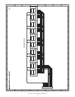
Page 23: ...1 10 a a b b c c d d e e f f g g dp dp LED9 LA56S2 S2 1 2 3 4 5 6 7 8 9 18 17 16 15 14 13 12 11 10 a a b b c c d d e e f f g g dp dp LED6 LA56S2 S2 1 2 3 4 5 6 7 8 9 18 17 16 15 14 13 12 11 10 R 3 0 30 1 6W R 3 2 30 1 6W R 3 1 30 1 6W 30 1 6W R 3 3 dp dp a a b b c c d d e e f f g g LED7 LA56S2 S2 1 2 3 4 5 6 7 8 9 18 17 16 15 14 13 12 11 10 R 3 5 30 1 6W R 3 4 30 1 6W R 3 6 30 1 6W A B C D 8 7 6 5...

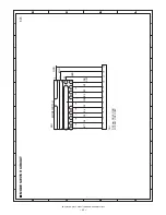
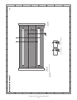
Page 24: ...MOR S3 S4 S5 S6 S7 0 000 00 1 2 3 4 5 6 7 8 9 10 CN1 P 2 0mm HOLE ONLY 8 9 10 11 12 13 5 1 7 2 4 6 3 A B C D 8 7 6 5 4 3 2 1 1 2 3 4 5 6 7 8 D C B A A B C D 8 7 6 5 4 3 2 1 1 2 3 4 5 6 7 8 D C B A A B C D 8 7 6 5 4 3 2 1 1 2 3 4 5 6 7 8 D C B A A B C D 8 7 6 5 4 3 2 1 1 2 3 4 5 6 7 8 D C B A 1 1 MODE SWITCH CIRCUIT ...

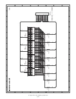
Page 25: ... dp a b c d e f g dp a g LED3 LA56S2 S2 4 17 18 1 2 3 15 16 9 7 12 5 6 8 10 11 14 13 a b c d e f g dp 3 8 5 10 9 1 2 4 6 7 LED4 LA56S1 S2 3 8 5 10 9 1 2 4 6 7 R8 27 1 6W R7 27 1 6W R6 27 1 6W R5 27 1 6W R4 27 1 6W R3 27 1 6W R2 27 1 6W R1 27 1 6W 13 14 11 8 6 5 7 9 12 16 15 3 2 1 18 17 4 10 b c d e f dp a b c d e f g dp a g LED1 LA56S2 S2 4 17 18 1 2 3 15 16 9 7 12 5 6 8 10 11 14 13 A B C D 8 7 6 ...

Page 26: ...2806 2610 1 2 3 4 5 6 7 8 9 10 11 12 13 14 15 16 17 18 19 20 21 22 23 24 25 26 C2 01 uF NOT MOUNT C1 0 1uF NOT MOUNT CN2 52806 2710 1 2 3 4 5 6 7 8 9 10 11 12 13 14 15 16 17 18 19 20 21 22 23 24 25 26 27 A B C D 8 7 6 5 4 3 2 1 1 2 3 4 5 6 7 8 D C B A A B C D 8 7 6 5 4 3 2 1 1 2 3 4 5 6 7 8 D C B A A B C D 8 7 6 5 4 3 2 1 1 2 3 4 5 6 7 8 D C B A A B C D 8 7 6 5 4 3 2 1 1 2 3 4 5 6 7 8 D C B A 1 1 ...

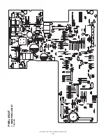
Page 27: ...XE A203U XE A203A CIRCUIT DIAGRAM AND PWB LAYOUT 25 PWB LAYOUT 1 MAIN PWB LAYOUT Top side ...

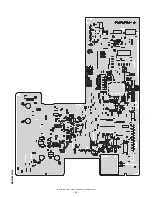
Page 28: ...XE A203U XE A203A CIRCUIT DIAGRAM AND PWB LAYOUT 26 Bottom side ...

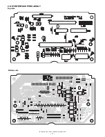
Page 29: ...XE A203U XE A203A CIRCUIT DIAGRAM AND PWB LAYOUT 27 2 KEY INTERFACE PWB LAYOUT Top side Bottom side ...

Page 30: ...XE A203U XE A203A CIRCUIT DIAGRAM AND PWB LAYOUT 28 4 REAR DISPLAY PWB LAYOUT 5 DISPLAY PWB LAYOUT 3 PRINTER I F PWB LAYOUT Top side Bottom side ...

Page 31: ... 2006 July Printed in Japan t COPYRIGHT 2006 BY SHARP CORPORATION All rights reserved Printed in Japan No part of this publication may be reproduced stored in a retrieval system or transmitted In any form or by any means electronic mechanical photocopying recording or otherwise without prior written permission of the publisher ...

Reviews: