VL-AD260U
8
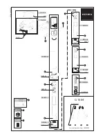
4-2. DISASSEMBLY OF THE VCR MAIN BODY
(1) Slide the “VCR lid knob” in the arrow direction, and slide the
VCR lid in the arrow direction as far as the cabinet L fastening
screw is visible. (Left figure) Since the connector of the
microphone is still connected, take care to prevent exces-
sively sliding the VCR lid.
<2. Disassembly of the cabinet L>
(3) Pull out the VCR lid shaft head which projects beyond the
surface of the VCR lid.
VCR lid shaft
VCR lid
Frame V
VCR lid shaft
<Detail of area A>
(2) Bring the jig (example: slotted precision screwdriver) into
contact with the removal groove of the VCR lid shaft, and
slide the screwdriver with care to prevent injuring the VCR lid
and frame V.
(1) Remove one screw ((k)LX-HZ0063TAFC).
(2) Remove five screws ((b)LX-HZ0018TAFF).
(3) Turn the tilt frame C so that the screwdriver can be easily
inserted, and remove two screws ((i)XiPSN20P04000).
(4) Remove one screw ((i)XiPSN20P04000).
Cabinet L
FPC connector
(b)
(i)
(i)
Area A
(k)
VCR lid knob
VCR lid
Tilt frame C
(5) Remove the cabinet L to the midway, and disconnect the FPC
connector.
<1. Removal of the VCR lid shaft>
Summary of Contents for VL-AD260U
Page 66: ...VL AD260U A B C D E F G H I J 1 2 3 4 5 6 7 8 9 10 85 VCR PWB Wiring Side SIDE A ...
Page 68: ...VL AD260U A B C D E F G H I J 1 2 3 4 5 6 7 8 9 10 87 VCR PWB Wiring Side SIDE B ...
Page 70: ...VL AD260U A B C D E F G H I J 1 2 3 4 5 6 7 8 9 10 89 CAMERA PWB Wiring Side SIDE A ...
Page 72: ...VL AD260U A B C D E F G H I J 1 2 3 4 5 6 7 8 9 10 91 CAMERA PWB Wiring Side SIDE B ...
Page 76: ...VL AD260U A B C D E F G H I J 1 2 3 4 5 6 7 8 9 10 95 HEAD AMP PWB Wiring Side SIDE A ...
Page 77: ...VL AD260U A B C D E F G H I J 1 2 3 4 5 6 7 8 9 10 96 HEAD AMP PWB Wiring Side SIDE B ...
Page 96: ...115 Ref No Part No Description Code Ref No Part No Description Code VL AD260U ...