10
VL-NZ50S/H/E/W/NZ80H
VL-NZ100S/H/E
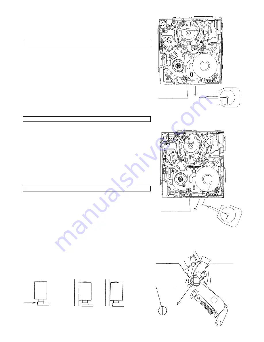
A
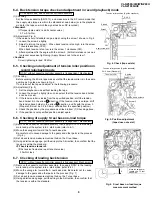
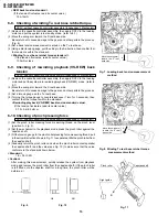
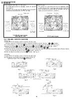
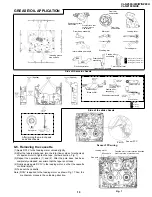
Fig. 7. Loading back tension measurement
method
Fig. 8. Winding Tu reel base ratchet torque
measurement method
Fig. 11
OK
NG
A
Fig. 10
Fig. 9
<REW back tension standard>
(If the tension fluctuates, read its center value.)
15
±
12mN
6-8. Checking of winding Tu reel base ratchet torque
DC3V, without cassette controller assembly (Independent Mechanism)
(1) Remove the cassette controller assembly, then apply DC3V to the loading
motor and put the system into standby mode. (refer to 8-1)
(2) Move the swing arm toward the S reel base side.
Be careful not to cause damage to the gears and other parts in the process.
(Fig. 8)
(3) Set a back tension measurement reel hub on the Tu reel base.
(4) Using a dial tension gauge, pull the string in the A direction, then confirm that
the tension is within the standard.
<Winding Tu reel base ratchet torque standard >
(If the tension fluctuates, read its center value.)
100mN or less
6-9. Checking of rewinding playback (VS-REW) back
tension
DC3V, without cassette controller assembly (Independent Mechanism)
(1) Remove the cassette controller assembly, then apply DC3V to the loading
motor and put the system into rewinding playback (VS-REW) mode. (refer to
8-1)
(2) Move the swing arm toward the S reel base side.
Be careful not to cause damage to the gears and other parts in the process.
(3) Set a torque gauge on the Tu reel base.
(4) Turning the torque gauge to counterclockwise (1 turn for 3 seconds), then
confirm that the torque is within the standard.
<Rewinding playback (VS-REW) back tension standard value>
(If the tension fluctuates, read its center value.)
0.70 +0.6/-0.3mN·m
6-10.Checking of pinch pressing force
DC3V, without cassette controller assembly (Independent Mechanism)
(1) Set the pinch roller pressing force measuring thread on the pinch lever
(position A , Fig. 9).
(2) Set the mechanism to the playback mode, press the pinch roller against the
capstan shaft.
(3) Fit the tension gauge to the pinch roller pressing force measuring thread, pull
in the arrow B direction shown in Fig. 11 to separate a little the pinch roller from
the capstan shaft.
(4) Gradually return the pinch roller, and when the pinch roller contacts parallel
the capstan shaft, read the value (see Fig. 10) to make sure that the value
conforms to the standard shown below.
<Standard>
1.8 +0.3/-0.5N
<Caution>
After making this measurement, quickly release the system from playback
mode and remove the pinch roller from the capstan shaft. (If the pinch roller
is left fitted onto the capstan shaft for a long time, the pinch roller will be
deformed.)
A
Move the swing arm
toward the S reel
base side.
Move the swing arm
toward the S reel
base side.
Capstan shaft
Pinch roller
B
Right guide


