7
7-1
7-2
SX76NF200
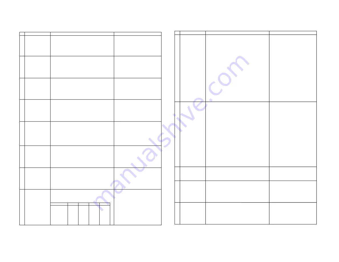
FUNCTION OPERATION CHECKING (1) (VIDEO & AUDIO)
NO
1
2
3
4
5
6
7
8
ADJUSTMENT POINT
CONTRAST
COLOUR
BRIGHTNESS
SHARPNESS
TINT
POWER SAVE
WHITE TEMP
NORMAL
ADJUSTMENT CONDITION / PROCEDURE
(1) Receive "Monoscope Pattern" signal.
(2) Press to Menu mode, then select Picture Mode and set
to select CONTRAST.
(3) Press Volume Up/Down key to check whether the
CONTRAST effect is OK or not.
(1) Receive "Colour Bar" signal.
(2) Press to Menu mode, then select Picture Mode and set
to select COLOUR.
(3) Press Volume Up/Down key to check whether the
COLOUR effect is OK or not.
(1) Receive "Monoscope Pattern" signal.
(2) Press to Menu mode, then select Picture Mode and set
to select BRIGHTNESS.
(3) Press Volume Up/Down key to check whether the
BRIGHTNESS effect is OK or not.
(1) Receive "Monoscope Pattern" signal.
(2) Press to Menu mode, then select Picture Mode and set
to select BRIGHTNESS.
(3) Press Volume Up/Down key to check whether the
BRIGHTNESS effect is OK or not.
(1) Receive "NTSC Colour Bar" signal thru AV in.
(2) Press to Menu mode, then select Picture Mode and set
to select TINT.
(3) Press Volume Up/Down key to check TINT, UP for
GREEN direction and DOWN for RED direction whether
is OK or not.
(1) Receive "Monoscope Pattern" signal.
(2) Set FEATURE to select SAVE.
(3) Press Volume Up/Down key to check the POWER SAVE
effect is OK or not. and whether LED(POWER SAVE)
light up or not.
(1) Receive "Monoscope Pattern" signal.
(2) Press to Menu mode, then select Picture Mode and set
to select WHITE TEMP.
(3) Press Volume Up/Down key to check WHITE TEMP
Option.
(1) Once in PICTURE Mode, and the NORMAL key is
pressed, all the settings will be present to normal setting.
(Normal setting value for every mode, refer on the
following figure).
WAVEFORM OR OTHERS
standerd
movie
music
news
CONTRAST
50
60
45
45
COLOUR
0
0
5
5
BRIGHT
0
5
5
0
TINT
0
0
0
0
SHARPNESS
0
0
0
0
PICTURE NR
LOW
LOW
LOW
LOW
WHITE TEMP.
0
10
0
0
CHECKING FUNCTION OPERATION (2) (VIDEO & AUDIO) CONTINUED
NO
9
10
11
12
13
ADJUSTMENT POINT
COLOUR SYSTEM
SOUND SYSTEM
VOLUME
BALANCE
BASS
ADJUSTMENT CONDITION / PROCEDURE
(1) Receive the "PAL COLOUR BAR" signal, press the
COLOUR SYSTEM key to select modes except PAL,
check the COLOUR is not working properly.
Then, select the "PAL" mode. Check again its colour so
that it is working properly.
(2) Receive "SECAM COLOUR BAR" signal, press
COLOUR SYSTEM key to select modes except SECAM,
check the COLOUR is not working properly.
Then, select the "SECAM" mode. Check again its colour
so that it is working properly.
(3) Receive "NTSC 3.58 COLOUR BAR" signal, press
COLOUR SYSTEM key to select modes except NTSC
3.58, check the COLOUR is not working properly.
Then, select the "NTSC 3.58" mode. Check again its
colour so that it is working properly.
(4) Receive "NTSC 4.43 COLOUR BAR" signal thru AV,
press COLOUR SYSTEM key to select modes
except NTSC 4.43, check the COLOUR is not working
properly.
Then, select the "NTSC 4.43" mode. Check again its
colour so that it is working properly.
(1) Receive "PAL-D/K" signal, press the "SOUND SYSTEM"
to select B/G, I, M Check the sound output is not working
properly.
Select D/K and check the sound output to make sure it is
working properly.
(2) Receive "PAL-I" signal, press the "SOUND SYSTEM"
to select B/G, D/K, M Check the sound output is not
working properly.
Select I and check the sound output to make sure it is
working properly.
(3) Receive "PAL-B/G" signal, press the "SOUND SYSTEM"
to select I, D/K, M Check the sound output is not
working properly.
Select B/G and check the sound output to make sure it is
working properly.
(4) Receive "NTSC-M" signal, press the "SOUND SYSTEM"
to select I, D/K, B/G Check the sound output is not
working properly.
Select M and check the sound output to make sure it is
working properly.
(1) Receive "E-5ch Monoscope Pattern" signal.
(2) Press Volume Up/Down key to check whether the
VOLUME effect is OK or not.
(1) Receive "E-5ch Monoscope Pattern" signal.
(2) Press to Menu mode, then select Sound Mode and set
to select BALANCE.
(3) Press Volume Up/Down key to check whether the
Left-to-Right BALANCE effect is OK or not.
(1) Receive "E-5ch Monoscope Pattern" signal.
(2) Press to Menu mode, then select Sound Mode and set
to select BASS.
(3) Press Volume Up/Down key to check whether the
BASS effect is OK or not.
WAVEFORM OR OTHERS
Summary of Contents for SX76NF200
Page 13: ...13 SX76NF200 WAVEFORMS ...
Page 14: ...14 SX76NF200 ...
Page 15: ...15 SX76NF200 ...
Page 16: ...16 SX76NF200 CHASSIS LAYOUT ...
Page 17: ...17 SX76NF200 ...
Page 18: ...18 SX76NF200 BLOCK DIAGRAM PWB A MAIN UNIT ...
Page 19: ...19 SX76NF200 ...
Page 20: ...20 SX76NF200 PWB B POWER UNIT ...
Page 21: ...21 SX76NF200 ...
Page 22: ...22 SX76NF200 PWB D IP UNIT ...
Page 23: ...23 SX76NF200 ...
Page 24: ...24 SX76NF200 PWB C CRT UNIT PWB E CONTROL UNIT ...
Page 25: ...25 SX76NF200 PWB F LED UNIT PWB H KEY UNIT ...
Page 27: ...A B C D E F G H I J 1 2 3 4 5 6 7 8 9 10 27 SX76NF200 CRT UNIT SCHEMATIC DIAGRAM ...
Page 28: ...A B C D E F G H I J 1 2 3 4 5 6 7 8 9 10 28 SX76NF200 MAIN UNIT 1 4 ...
Page 29: ...10 11 12 13 14 15 16 17 18 19 29 SX76NF200 ...
Page 30: ...A B C D E F G H I J 1 2 3 4 5 6 7 8 9 10 30 SX76NF200 MAIN UNIT 2 4 ...
Page 31: ...10 11 12 13 14 15 16 17 18 19 31 SX76NF200 ...
Page 32: ...A B C D E F G H I J 1 2 3 4 5 6 7 8 9 10 32 SX76NF200 MAIN UNIT 3 4 ...
Page 33: ...10 11 12 13 14 15 16 17 18 19 33 SX76NF200 ...
Page 34: ...A B C D E F G H I J 1 2 3 4 5 6 7 8 9 10 34 SX76NF200 MAIN UNIT 4 4 ...
Page 35: ...A B C D E F G H I J 1 2 3 4 5 6 7 8 9 10 35 SX76NF200 LED UNIT KEY UNIT ...
Page 36: ...A B C D E F G H I J 1 2 3 4 5 6 7 8 9 10 36 SX76NF200 POWER UNIT ...
Page 37: ...10 11 12 13 14 15 16 17 18 19 37 SX76NF200 ...
Page 38: ...A B C D E F G H I J 1 2 3 4 5 6 7 8 9 10 38 SX76NF200 IP UNIT ...
Page 39: ...10 11 12 13 14 15 16 17 18 19 39 SX76NF200 ...
Page 40: ...A B C D E F G H I J 1 2 3 4 5 6 7 8 9 10 40 SX76NF200 CONTROL UNIT ...
Page 41: ...10 11 12 13 14 15 16 17 18 19 41 SX76NF200 ...
Page 43: ...10 11 12 13 14 15 16 17 18 19 43 SX76NF200 ...
Page 44: ...A B C D E F G H I J 1 2 3 4 5 6 7 8 9 10 44 SX76NF200 PWB A MAIN UNIT Chip Parts Side ...
Page 45: ...10 11 12 13 14 15 16 17 18 19 45 SX76NF200 ...
Page 46: ...A B C D E F G H I J 1 2 3 4 5 6 7 8 9 10 46 SX76NF200 PWB B POWER UNIT Wiring side ...
Page 47: ...10 11 12 13 14 15 16 17 18 19 47 SX76NF200 ...
Page 48: ...A B C D E F G H I J 1 2 3 4 5 6 7 8 9 10 48 SX76NF200 PWB C CRT UNIT Wiring side ...
Page 50: ...A B C D E F G H I J 1 2 3 4 5 6 7 8 9 10 50 SX76NF200 PWB E CONTROL UNIT Wiring side ...


