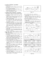
PLAYBACK SENSITIVITY ADJUSTMENT
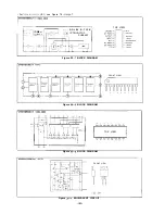
(See Figure 6-l
1. Connect VTVM between test point
(or TP203)
and ground.
2. Push the tape selector switch SW4 and set the Dolby
switch SW3 at off position.
3. Put a test tape (TEAC, MTT-150,400 Hz, 200
recorded) into the unit and play it.
4. Adjust semi-variable resistor
(or
so that
580
will be indicated on VTVM.
n
RECORD/PLAYBACK SENSITIVITY ADJUSTMENT
(See Figure 6-2) SW7 is not used for model RT-31H.
1. Connect VTVM between test point TP103 (or TP203)
and ground.
2. Connect CR oscillator to the line input socket, and
apply the signal of oscillation frequency 400 Hz, output
level -13
(0
to the unit.
3. Push tape selector switch SW4 and set the Dolby
switch SW3 at off position.
4. Put a normal tape (TEAC, MTT-502, blank) into the
unit, and place it in record mode. Adjust the record
level control
(or
so that the reading
of VTVM becomes 390
5. Playback the normal tape which has been recorded
in the step 4, and adjust the semi-variable resistor
(or VR203) so that the reading of VTVM be-
comes 410
Repeat the steps 4 and 5 until the
VTVM reading stays in the range from 360
to
460
6. Put a
tape (MAXELL, UDXL
into the unit.
7. Push the tape selector switch SW5, and place the unit in
record mode.
8. Playback the
tape which has been recorded in the
step 7, and make sure VTVM indicates the reading
within 326
to 487
PEAK LEVEL DISPLAY METER SENSITIVITY ADJUST-
MENT
(See Figure 6-3)
Connect VTVM between test point
02 (or
and ground.
2. Set the Dolby
switch SW3 at off position and
input selector switch SW2 at “LINE” position.
3. Connect CR oscillator to the line input socket, and
apply the signal of oscillation frequency
316
(-10
to the unit, placing it in record mode.
4. Adjust record level control VR102 (or VR202) so that
VTVM will indicate 580
(-4.7
5. Change the output level of CR oscillator from 316
( - 1 0
to 305
(-10.3
t h e n a d j u s t t h e
resistor VR601 (or
so that the
segments
up to 0
of the peak level display
meter light up.
6. Again change the output level of CR oscillator from
305
(-10.3
to 295
(-10.6
then see
that the segments up to -3
remain lit.
n
DOLBY NOISE REDUCTION CIRCUIT CHECK
(See Figure 6-4)
1. Connect VTVM between test point
03 (or
and ground.
2. Push the tape selector switch SW4, and set the input
s e l e c t o r s w i t c h
at LINE
switch SW3 at off position.
3. Connect CR oscillator to the line input socket, and
apply the signal of oscillation frequency
Hz, output
level -35
(0
1
to the unit.
Figure 6-l
9. Put a metal tape (TDK, AC-71 into the unit.
Push the tape selector switch SW6, and place the unit
in record mode.
11. Playback the metal tape which has been recorded in the
step
and make sure VTVM indicates the reading
within 326
to 487
12. Put a Fe-Cr tape (SONY, CS-30) into the unit.
13. Push the tape selector switch SW7 and place the unit
in record mode.
14. Playback the Fe-Cr tape which has been recorded
in the step
and make sure VTVM indicates the
reading within 326
to 487
Figure 6-2
Figure 6-3
Frequency
10
12.5
Indicated
45.7 to
44.5 to
42.6 to
Value
81
70
68.2
Table
Frequency
1
12.5
Indicated
8.2 to
13.7 to
13.5 to
Value
16.4
24.9
23.4
Table 2
Figure 6-4


