background image

 (Photographs of RT-31H)

Prior to the disassembly, be sure to remove the AC supply
cord from a wall outlet and the input/output plugs from the
rear of the set. Take out a cassette tape, if loaded in the
cassette compartment,

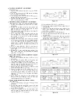
 REMOVAL OF CABINET 

(See Figures 

 and 

From the cabinet, remove four screws two each at its
right and left sides, and one screw at its rear surface.

Then take the cabinet off.

Figure 2-l

REMOVAL OF BOTTOM PLATE 

(See Figure 2-3)

Turn the set upside down, remove two screws from the
bottom plate, and take the bottom plate off by shifting

it in the arrow direction.

REMOVAL OF FRONT PANEL

(See Figures 2-4 and 2-5)

Remove four screws from the front panel.

2 Push down three stoppers at the upper surface of the

front panel, See that the front panel is now free from
the stoppers.

 Pull the front panel frontwards.

Figure 2-4

REMOVAL OF MECHANISM BLOCK

(See Figures 2-6 and 

Note:
Be sure to open the cassette compartment lid before

disassembling the mechanism block,

1

Remove two screws from the bottom of the set.

2 Remove two screws from the rear of the mechanism

block.

 Detach the tape counter belt from the tape counter.

4 Remove the record/playback selector switch rod.
5 Remove four sockets from the mechanism block P.W.

board. Then separate the mechanism block from the set.

Figure 2-2

Figure 2-3

Figure 

Figure 

Summary of Contents for RT-31

Page 1: ...OLBY SYSTEM Noise reduction system manufactured under license from Dolby Laboratories Licensing Corporation Dolby and the double D symbol are trademarks of Dolby Laboratories Licensing Corporation RT 31 For SEC RT 31 H For SEEG SUK SCA and General RT 31 HB For SEW In the interests of user safety the set should be restored to its original condition and only parts identical to those specified by use...

Page 2: ... arrow direction n REMOVAL OF FRONT PANEL See Figures 2 4 and 2 5 1 8 Remove four screws from the front panel 2 Push down three stoppers at the upper surface of the front panel See that the front panel is now free from the stoppers Pull the front panel frontwards Figure 2 4 n REMOVAL OF MECHANISM BLOCK See Figures 2 6 and 3 l Note Be sure to open the cassette compartment lid before disassembling t...

Page 3: ...he unit is designed to operate from IIOV 22OV or 24OV AC mains Check the voltage selector setting on the rear panel before connecting with the AC supply cord Adjust the voltage selector to match your local AC power supply The voltage selector is located on the rear panel of the unit If adjustment is necessary use a screwdriver in order to turn the selector in either direction until the correct vol...

Page 4: ...is not satisfied adjust the pinch roller pressure spring by bending it or replace n TORQUE CHECK AT PLAY FAST FORWARD AND REWIND MODES 1 Put a torque measuring cassette into the set 2 The torque values in each mode must be as tabulated below n TAPE SPEED ADJUSTMENT 1 Using a test tape TEAC MTT 113C 8 kHz record ed play it back at the midpoint but not at the running start or end point 2 Connect a f...

Page 5: ...W6 4 Place the unit in record mode then see that VTVM is value 210 mV n RECORD PLAYBACK HEAD AZIMUTH ADJUSTMENT See Figure 5 3 1 Connect VTVM between the test point TP103 or TP203 and ground 2 Push the tape selector switch SW4 and set the Dolby NR switch SW3 at off position 3 Put a test tape TEAC MTT 114 IO kHz 250 pWb mm 10 dB recorded into the unit and play it 4 Adjust the head azimuth adjusting...

Page 6: ... selector switch SW2 at LINE position 3 Connect CR oscillator to the line input socket and apply the signal of oscillation frequency 1 kHz 316 mV 10 dB to the unit placing it in record mode 4 Adjust record level control VR102 or VR202 so that VTVM will indicate 580 mV 4 7 dB 5 Change the output level of CR oscillator from 316 mV 10 dB to 305 mV 10 3 dB then adjust the semivariable resistor VR601 o...

Page 7: ...5 Give the set 1 kHz signal 10 kHz signal and 12 5 kHz level control VR102 or VR202 so that VTVM will indicate 5 8 mV signal one after another then see that VTVM indicates the reading listed in Table 1 7 In the same manner as in the step 5 give the set 1 kHz signal 10 kHz signal and 12 5 kHz Consequently make sure VTVM indicates the reading listed in Table 2 ALIGNMENT POINTS Figure 7 l VHILA3160 1...

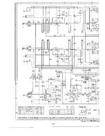
Page 8: ... 2SCl214C P70 I 2SA733K MARKING SIDE Specifications or wiring diagrams of this model L 7 2 I FILIOI FI L20 I NOTES 0 7 0 2 2SD794P 1 are subject to change for improvement without prior notice 3 I 4 5 I 6 Figure 9 SCHEMATIC c ...

Page 9: ...sed the symbol K used this symbol P means micro microfar specified ones for main taining the means 1000 ohm and the symbol M means and the unit of the capacitor without sur safety and performance of the set lOOOK ohm and the resistor without any symbol is microfarad A s t o electrolyt symbol is ohm type resistor Besides the one capacitor the expression capacitance wit with Fusible is a fuse type s...

Page 10: ...1 2 3 I 4 5 6 r E F G H rLiNE 1 _ r 1 2 3 4 I 5 6 I Figure 11 WIRING SIDE OF PRINT ll ...

Page 11: ...7 8 9 10 11 12 4 A AV II II I II II f h B 3 C D I I _ ____ A 1 E F G H 7 I 8 I 9 10 I 11 I 12 IF PRINTED WIRING BOARD RT91H HB 1 2 ______ _ _ __ _ ...

Page 12: ...70 I 2SA733K MARKING SIDE 301 0302 2SCl214C 0702 2507940 FILIOI FIL201 NOTES Pa PC se LoM SP sa Specifications or wiring diagrams of this model are subject to change for improvement without prior notice 1 I 2 I 3 I 4 I 5 I 6 Figure 13 SCHEMATIC DIL 13 ...

Page 13: ...ace these parts with symbols as K and M are used the symbol K used this symbol P means micro microfarao specified ones for main taming t h e means 1000 ohm and the symbol M means and the unit of the capacitor without suer safety and performance of the set IOOOK ohm and the resistor without any symbol is microfarad As to electrolytic svmbol is ohm Woe resistor Besides the one capacitor the expressi...

Page 14: ... s w I A r a a o mo mo c 3 a o 8 L N M _ C X J i i CT 1 t zf A x G c m 1 2 3 I 4 5 6 I Figure 15 WIRING SIDE OF PRI 15 ...

Page 15: ...7 8 9 10 11 12 i I ___ L _ __ _ __ I 11 SW I SWIZ PIPS SWlTCH BIAS SWlTCH 1 I II I 1 I LEFT MIC I I _1_ I 7 I 8 I 9 I 10 I 11 I 12 llTED WIRING BOARD RT 31 16 ...

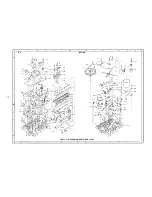
Page 16: ...I TOP G n m 0 0 m D 1 BOTTOM Figure 17 MECHANISM EXPLODED VIEW ll In 0 0 m D ...

Page 17: ...1 2 3 4 5 6 I1 I Y 0 L t A 2 J 3s c p ii E F 01 504 3 1 A B C D E F G H I 2 3 4 5 6 Figure 18 CABINET EXPLODED VIEW Use of RTSlH HB 18 ...

Page 18: ...ansistors Diodes Zener Diode and LED described in this parts list they are different according to the Model RT 31 H HE or RT 31 A distinction is drawn between the abovedescribed items by description of the used units parenthesized NOTES Parts marked with Q I are important for maintaining the safety of the set Be sure to replace these parts with specified ones for maintaining the safety and perform...

Page 19: ... L B Y B T Y P E OWE R CIRCUIT TOP VIEW N C i OUTPUT 01 OUTPUT u INPUT REFERENCE OUTPUT N IN PUT INPUT Figure 20 I BLOCK DIAGRAM VHIIR3108 1 IC4 FRONT VIEW Figure 20 2 BLOCK DIAGRAM TOP VIEW Figure 20 3 BLOCK DIAGRAM VHIHA178M15 1 IC7 FRONT VIEW Figure 20 4 EQUIVALENT CIRCUIT ...

Page 20: ...1 2 I 3 4 5 6 _ b _ 2 i F G H 1 I 2 3 4 5 6 Figure 19 CABINET EXPLODED VIEW Use of RT 31 19 A B C D E ...

Page 21: ...ecord Level Control RVR M0328AFZZ 50K ohm B Record Sensitivity Adjust RVRM0263AFZZ 20K ohm B Bias Current Adjust RVR M0328AFZZ 50K ohm B Peak Level Display Meter Sensitivity Adjust ELECTORIC CAPACITORS VCEALAlCClOGM lOMFD 16V 120 RCEZA107AFl A IOOMFD lOV r20 RC EZA335AFl H 3 3MFD 50V 20 VCEALAI HW224M 22MFD 50V f20 RCEZV227AFl C 220MFD 16V 20 RC EZAlOGAFlC IOMFD 16V _20 VCEALAlHW104K lMFD 5OV lO V...

Page 22: ...cification Sheet RT 31 HI AC TSPCO740AFZZ Specification Sheet AC RT 31 HB TSPC0741AFZZ Specification S h e e t RT 31 A B PF LTB330AFOO Felt Cabinet A A PSPAB0103AFFW Spacer Voltage Selector A A Socket RT 31 H HB 2 4 1 242 243 REF NO PART NO DESCRIPTION CODE 245 h iTi d Lr lQ 2 in Str Pin j 1 q rr j_ I 6 lrpply Card RT31 H HB pY 1 245 LANG F041 ZAFZZ Spacer Transformer A A Reinforcement RT 31 H HB ...

Page 23: ...MSPRT0746AFFJ 080 MSPRT0747AFFJ 081 NBALS0006AGFJ 082 NBLTHOO76AFZZ 083 NBLTK0184AFZZ 084 NDAIR0150AFSA 085 NDAIROl51AFSA 086 NFLYCOOQOAFZZ 087 NGERH0066AFZZ 088 NGERH0067AFZZ 089 NGERP0051 AFZZ 090 NIDR 0073AFZZ 091 NIDR 0074AFZZ 092 NPLY ROO76AFZZ 093 NROLV0017AFZZ 094 NROLX0014AFZZ 095 NROLY0037AFZ Z 096 NSFTN0008AFFW 097 NSFTTOI 48AFFW A B A B A B A A A C A AG AE AP A A E A A D A B A A F A F A...

Page 24: ...A B AA A A A B A A A A A A AB A A A A A A A A AB A A A A A A A A 2 3 IREF NO R612 613 R701 R702 R703 R704 R705 R706 R707 R708 R709 R710 R711 001 PART NO DESCRIPTION CODE VRDST2EE822J VRDST2EEl03J VRD ST2EE152J VRDST2EE181J VRDST2EE822J VRDST2EE273J VRDST2EE121J VRDST2EE222J VRDST2EE223J V RDST2EE222J VRDST2EE223J VRDST2EE821J 8 2K ohm 10K ohm 1 5K ohm 180 ohm 8 2K ohm 27K ohm 120 ohm 2 2K ohm 22K ...

Page 25: ...eplacement item DUNTU0070AF03 M a i n C i r c u i t P o w e r S w i t c h Combined Assembly Circuit Peak Level Indi cator Circuit RT31 H HB DUNTU0070AF09 M a i n C i r c u i t P o w e r S w i t c h Combined Assembly Circuit Peak Level Indi cator Circuit RT 31 Figure 26 AC SUPPLY CORD WIRING CONNECTIONS SHARP CORPORATION OSAKA JAPAN SHARP ELECTRONICS CORPORATION Executive Offrce 10 Keystone Place P...

Reviews: