background image

POUR LA DESCRIPTION COMPLETE DU 
N E M E N T   D E   C E T  

  S E   R E P O R T E R   A U

MODE D’EMPLOI.


  B E S C H R E I B U N G   D E R  


 IN DER 

 ENTHALTEN.

 DATEN

Riemenantrieb halbautomatisch

8 Transistoren

2 dioden
3 Hall Elements

Drehzahlen:


 45 

Motor:

Gleichstromservomotor

Gleichlaufschwankungen: 

 (DIN 45 500)

Rauschabstand:

65 

 (DIN 

Ausgang:


 50 

Frequenzgang:

 000 Hz

Auflagekraft:

2.5 
Gewichtsbalanciert

Tonabnehmersystem:

Magnetischer Typ (CART-1371

Ersatznadel:

STY-l 37

Abmessungen:

Breite: 430 mm


  m m

Tiefe: 367 mm

Gewicht:

2.5 kg

Die technischen Daten 

 dieses 


 ohne 

herige 


 unterworfen sein.

 DER 


 17 

2. Mittelachse

Plattentellerblatt

4. Plattenteller
5.
6.
7. Tonarmlifthebel
8. Tonabnehmersystem
9. Unterbrechungstaste: CUT

10. Drehzahlwahltaste: SPEED
11.

Type 

Entrainement direct,

semi-automatique

Semiconducteur:

8 Transistors
2 Diodes

   effet Hall

Vitesse:

33 

 et 45 t/mm

Moteur:

Servo-moutter CC

Pleurage et scintillement:

 (DIN 45 500)

Rapport 

65 

 (DIN 

Sortie:


 50 mm/s)

 de 

20   20.000 Hz

Force d’appui:

2.5   

Bras de lecture:

 statique

Type 

 (CART-1371

 de remplacement: STY-137

Dimensions:

Largeur: 430 mm
Hauteur: 108 mm

Profondur: 367 mm

Poids:

2.5 kg

Les 

 de ce 

 sont 

   modifica-

tion 


NOMENCLATURE

1. Adaptateur de 

 45 tours

2. Mandrin central
3. 

 de plateau

4. Plateau

5. Bras de lecture
6. Contrepoids 
7. Levier de mise en pile
8.
9. 

 de 

 CUT


 de selection de vitesse: SPEED

11. Fiche 

Summary of Contents for RP-32 Series

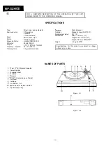
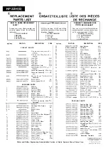
Page 1: ...AMESOFPARTS a 2 3 SCHEMATIC DIAGRAM AND WIRING CARTIRDGE REPLACEMEMT 4 SIDE OF P W BOARD IO PACKING METHOD FOR UK 5 EXPLODED VIEW 11 DlSASSEMBLY 6 7 REPLACEMENT PARTS LIST 12 MECHANICAL ADJUSTMENT 6 7 INHALTSVERZEICHNIS Seite Seite TECHNISCHE DATEN 2 3 SCHEMATISCHER SCHALTPLAN UND BEZEICHNUNG DER TEILE 2 3 VERDRAHTUNGSSEITE D E R LEITERPLATTE 10 AUSWECHSELN DES TONABNEHMERSYSTEMS 4 EXPLOSIONSDARST...

Page 2: ...t 20 20 000 Hz 2 5 g recommended 1 17 cm 7 EP Record Adaptor 2 Center Spindle 3 Turntable Sheet 4 Turntable 5 Tonearm 6 Tonearm Counterbalance Weight 7 Cue Lever 8 Cartridge 9 Cut Button Cut 10 Speed Selector Button SPEED 11 Input Output Plug SPECIFICATIONS Tonearm Static balanced Cartridge Magnetic type CART 137 Replacement stylus STY 137 Dimensions Width 430 mm 17 Height 108 mm 4 l 4 Depth 367 m...

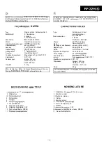
Page 3: ...ttelachse 3 Plattentellerblatt 4 Plattenteller 5 Tonarm 6 Tonarm Gegengewicht 7 Tonarmlifthebel 8 Tonabnehmersystem 9 Unterbrechungstaste CUT 10 Drehzahlwahltaste SPEED 11 Eingangs IAusgangsstecker CARACTERISTIQUES Type Entrainement direct semi automatique Semiconducteur 8 Transistors 2 Diodes 3 Cellules 2 effet Hall Vitesse 33 l 3 et 45 t mm Moteur Servo moutter CC Pleurage et scintillement 50 08...

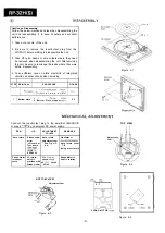
Page 4: ...re 6 l S T E P R E M O V A L PROCEDURE FIGURE 1 1 Turntab e 1 l Turntablesheet Alxl 1 6 2 Turntable s t o p p e r B xl Bottom plate 1 Screw C x3 2 Bottom Plate stopper D xl 6 2 J MECHAN I CAL ADJUSTMENT TOP VIEW Connect the Input output plug to the amplifier SM 32H E or supply 12V by an external DC power supply REMARKS ITEM JIG Bladed screw driver LP record or Test record SSR 4001 SIDE 1 SSR4002 L...

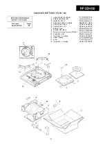
Page 5: ...ne Bag Turntable SSAKP048 1 AFZZ Packing Add Right SPAKAI 286AFZZ Packing Add Left SPAKAI 285AFZZ Packing Case SPAKC3075AFZZ Packing Add Back SPAKX1409AFZZ Polyethlyene Bag Tonearm Weight SPAKA0036AFZZ Protection Arm SPAKX1326AFZZ Protection Turntable SPAKAI 298AFZZ Label Caution TCAUZ0039AFZZ Label TLABP0295AFZZ Protection Turntable SPAKX 1407AFZZ ...

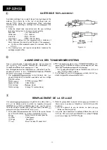
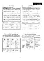
Page 6: ...mersystems in den Tonabnehmertrager des Modelles dem Tonarm entfernt werden RP 32H E aufmerksam durchlesen 3 Die Auflagekraft mu6 nueu eingestellt werden da die Ton 1 Die Ausgangsleitungsanschliisse in die Klemmen des Ton abnehmergewichte unterschiedlich sind abnehmersystems einsetzen und dabei auf die richtige Polaritlt achten Blaue Leitung Erdung fiir linken Kanal Weil3e Leitung Linker Kanal Rot...

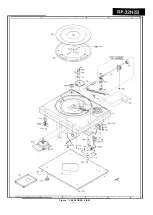
Page 7: ...I I I 2 I 3 I 4 I 5 1 6 05 I 12 IO Figure 11 EXPLODED VIEW ll ...

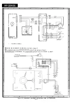
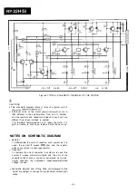
Page 8: ...L ch I I 0 IE NOTES ON SCHEMATIC DIAGRAM can be found on page 8 0 D ANMERKUNGEN ZUM SCHEMATISCHEN SCHALTPLAN stehen auf Seite 9 OREMARQUES CONCERNANT LE DIAGRAMME SCHEMATIQUE sont indiqub g la page 9 Figure 10 SCHEMATIC DIAGRAM AND WIRING SIDE OF P W BOARD 1 o ...

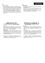
Page 9: ...benutzt l Anderungen des schematischen Schaltplans und der Ver drahtungsseite der Leiterplatte fiir dieses Model1 im Sinne von Verbesserungen jederzeit vorbehalten PI CAUTIONS l Ce diagramme schematique est base sur celui du moteur RMoTV0184AFZZ 9 La performance du moteur RMoTV0184AFZZ varie legerement selon les unites II en va de m me pour les resis tances et condensateurs utilises dans le moteur...

Page 10: ...utout A C Lever Cutout A C Spring Plate Type A B PART NO 23 NGERHO132AFZZ 24 NTNT 0069AFSA 25 PCoVP9164AFZZ 27 PCUSG0256AFZZ 28 PEPAP0053AFSA 29 PSHEG0061AFSA 30 PSPAZOlSOAFZZ 31 TLABG0273AFZZ 31 TLABG0274AFZZ 31 TLABG0275AFZZ 31 TLABG0276AFZZ 32 TLABH0266AFZZ 32 TLABH0267AFZZ 32 TLABH0272AFZZ 32 TLABH0275AFZZ 33 LSTWC3002AFZZ 34 LSTWC4004AFZZ 35 LSTWC2403AFZZ 701 XHBSD30P14000 702 XJBSD30P08000 7...

Page 11: ...re different from those included in another It is therefore recommended not to repair the motor if it gets in trouble In such case replace it with the new one NOTES ON SCHEMATIC DIAGRAM 0 Resistor To differentiate the units of resistors such symbol as K is used the symbol K means 1000 ohm and the resistor without any symbol is ohm type resistor 0 Capacitor To indicate the unit of capacitor a symbo...

Page 12: ... ENTFERNEN VERFAHREN TAPE DiPOSE PROCiDi FIGURE 1 Plateau 1 Feuille du 1 Plattenteller l Plattenteliermatte A xl 2 Placttenteller 6 l Anschlag 6 x1 2 Bodenpiatte 1 Schraube C x3 2 Bodenplatte 6 2 Anschlag D xl MECHANISCHE EINSTELLUNG Den Eingangs IAusgangsstecker an den Verstarker SM 32 H E anschlieaen o d e r durch eine AuRengleichspannung 12V zuleiten REGLAGE MECANIQUE Brancher la fiche d entr e...

Reviews: