background image

35

R-3A56

Note: The parts marked "

" may cause undue microwave exposure.

The parts marked "*" are used in voltage more than 250V.

REF. NO.

PART NO.

DESCRIPTION

Q'TY

CODE

HOW TO ORDER REPLACEMENT PARTS

To have your order filled prompty and correctly, please furnish the following information.

1. MODEL NUMBER

2. REF. NO.

3. PART NO.

4. DESCRIPTION

7- 7

LX-CZA038WRE0

Special screw

2

AA

7- 8

LX-CZ0052WRE0

Special screw

4

AA

7- 9

XFPSD30P06000

Screw; 3mm x  6mm

2

AA

7-10

XFPSD40P06000

Screw; 4mm x  6mm

3

AA

7-11

LX-CZA029WRE0

Special screw

3

AA

7-12

XFPSD40P08000

Screw; 4mm x  8mm.

4

AA

7-13

XHTSD40P08000

Screw; 4mm x  8mm

1

AA

Summary of Contents for R-3A56

Page 1: ... OVEN TABLE OF CONTENTS Page CAUTION MICROWAVE RADIATION 1 WARNING 1 PRODUCT SPECIFICATIONS 2 GENERAL INFORMATION 2 APPEARANCE VIEW 3 OPERATION SEQUENCE 4 FUNCTION OF IMPORTANT COMPONENTS 5 SERVICING 7 TEST PROCEDURE 9 TOUCH CONTROL PANEL 16 COMPONENT REPLACEMENT AND ADJUSTMENT PROCEDURE 21 MICROWAVE MEASUREMENT 26 WIRING DIAGRAM 27 PICTORIAL DIAGRAM 29 CONTROL PANEL CIRCUIT 31 PRINTED WIRING BOAR...

Page 2: ...R 3A56 ...
Page 3: ...sed to the microwave energy which may radiate from the magnetron or other microwave generating devices if it is improperly used or connected All input and output microwave connections waveguides flanges and gaskets must be secured Never operate the device without a microwave energy absorbing load attached Never look into an open waveguide or antenna while the device is energized WARNING Never oper...

Page 4: ...ency 2450 MHz Case Dimensions Width 520 mm Height 305 mm including foot Depth 385 mm Cooking Cavity Dimensions Width 348 mm Height 197 mm Depth 368 mm Turntable diameter 325mm Control Complement Touch Control System Clock 1 00 12 59 Timer 0 99 minutes 99 seconds Microwave Power for Variable Cooking Repetition Rate HIGH Full power throughout the cooking time MEDIUM HIGH approx 70 of Full Power MEDI...

Page 5: ...orquantityoffood or toselecttheAutocookmenus EASYDEFROSTPAD Presstodefrostmeatbyentering weightonly Reheat Beverage 1 cup Reheat Pizza 1 piece Reheat Pie 1 piece 1 2 3 4 5 POWER LEVEL EASY DEFROST LESS MORE 2 X 3 X 4 X AUTOCOOKPAD PresstoselectAutoCookmode AUTOCOOKMENUS POWERLEVELPAD Presstoselectmicrowavepower setting Ifnotpressed HIGHis automaticallyselected 2 3 or4SERVEQUANTITYPAD Tocooktwo thr...

Page 6: ...es come to the following condition CONDITION DURING DOOR OPEN SWITCH CONTACT COOKING NO COOKING 1st latch switches COM NO Closed Open 2nd latch switch COM NO Closed Open Monitor switch COM NC Open Closed Stop switch COM NO Closed Open The circuits to the power transformer fan motor and turntable motor are cut off when the 1st latch switch 2nd latch switch and stop switch are made open The oven lam...

Page 7: ...of D2 of the asymmetric rectifier is 1 7 KV D1 and D2 of the asymmetric rectifier or high voltage rectifier are shorted when the each peak reverse voltage goes beyond the each rated peak reverse voltage The process of blowing the fuse M8A 1 The high voltage rectifier is shorted by any causes when microwave cooking 2 The peak reverse voltage of D2 of the rectifier goes beyond the rated peak reverse...

Page 8: ...ermal cut out will open and switch off the oven When the oven cools itself down to 75 C the contacts of the thermal cut out will close again TURNTABLE MOTOR The turntable motor drives the turntable roller assembly to rotate the turntable FAN MOTOR The fan motor drives a blade which draws external cool air This cool air is directed through the air vanes surrounding themagnetronandcoolsthemagnetron ...

Page 9: ...arry out 3D checks and reconnect the leads to the primary of the power transformer REMEMBER TO CHECK 4R 1 Reconnectallleadsremovedfromcomponentsduring testing 2 Replace the outer case cabinet 3 Reconnect the supply 4 Run the oven Check all functions Microwave ovens should not be run empty To test for the presence of microwave energy within a cavity place a cup of cold water on the oven turntable c...

Page 10: ...AR pad is touched Oven lamp does not light at door opened Display appears Oven does not start when the START pad is touched Display appears Oven lamp does not light Display appears Fan motor does not operate Dis play appears Turntable motor assembly does not operate Display appears Oven or any electrical parts does not stop when cooking time is 0 or STOP CLEAR pad is touched Oven seems to be opera...

Page 11: ...ows P x t 4 187 V x T P W 4 187 x V x T t Our condition for water load is as follows Room temperature around 20 C PowersupplyVoltage Ratedvoltage Water load 1000 g Initial temperature 10 2 C Heating time 49 sec P 85 x T Measuring condition 1 Container The water container must be a cylindrical borosilicate glass vessel having a maximum material thickness of 3 mm and an outside diameter of approxima...

Page 12: ...h V ml rises T C during this microwave heating period the calorie of the water is V x T The formula is as follows P 8330 x T Our condition for water load is as follows Room temperature around 23 2 C Power supply Voltage Rated voltage Water load 2000 ml Initial temperature 23 1 C Heating time 1 min 51sec P 75 x T Measuring method A The two water containers must be prepared The water container must ...

Page 13: ...nd should be replaced CARRY OUT 4R CHECKS C HIGH VOLTAGE RECTIFIER ASSEMBLY TEST HIGH VOLTAGE RECTIFIER TEST CARRY OUT 3D CHECKS Isolate the high voltage rectifier assembly from the HV circuit The high voltage rectifier can be tested using an ohmmeter set to its highest range Connect the ohmmeter across the terminal B C of the high voltage rectifier and note the reading obtained Reverse the meter ...

Page 14: ...nuity for a short time kick and then a resistance of about 10MΩ after it has been charged D A short circuited capacitor shows continuity all the time E An open capacitor constantly shows a resistance about 10 MΩ because of its internal 10MΩ resistance F When the internal wire is opened in the high voltage capacitor shows an infinite resistance G The resistance across all the terminals and the chas...

Page 15: ...rs Resistance Fan motor Approximately 370 Ω Turntable motor Approximately 16 08 kΩ If incorrect readings are obtained replace the motor CARRY OUT 4R CHECKS J TOUCH CONTROL PANEL ASSEMBLY TEST The touch control panel consists of circuits including semiconductors such as LSI ICs etc Therefore unlike conventional microwave ovens proper maintenance cannot be performed with only a voltmeter and ohmmete...

Page 16: ...g switch stop switch is good disconnect the flat ribbon that connects the key unit to the control unit and make sure the door sensing switch is closed either close the door or short the stop switch connecter Use the key unit matrix indicated on the control panel schematic and place a iumper wire between the pins that correspond to the STOP CLEAR pad making momentary contact If the control unit res...

Page 17: ... NOISE FILTER TEST If incorrect readings are obtained replace the noise filter unit CARRY OUT 4R CHECKS CARRY OUT 3D CHECKS Disconnect the leads from the terminals of the noise filter Using an ohmmeter check between the terminals as described in the following table L min Cx 20 Cy 20 1 0 mH 0 068µF 0 0022µF MEASURING POINT INDICATION OF OHMMETER Between N and L Open circuit Between terminal N and W...

Page 18: ...ol Voltage Application VC 5V LSI IC1 VP 30V Fluorescent display tube Grid and anode voltage VF1 2 2Vac Filament of fluorescent display tube VF2 VF1 to VF2 voltage 3 Synchronizing Signal Circuit The power source synchronizing signal is available in order to compose a basic standard time in the clock circuit It accompanies a very small error because it works on commercial frequency 4 ACL Circuit A c...

Page 19: ...the ceramic filter oscillation circuit with respect to OSC1 terminal 9 OSC2 OUT Internal clock oscillation frequency control output Output to control oscillation input of OSC2 10 11 GND AVSS IN IN Connected to VC 12 AN0 OUT Oven lamp turntable motor and cooling fan motor driving signal Square Waveform 50Hz To turn on and off the control relay The pulse signal 50Hz is delivered to the control relay...

Page 20: ...al Refer to the touch control panel circuit for the relationship between signals and indicators Normally one pulse is output in every synchronized signal period and input to the anode of the fluorescent display 32 R81 OUT Segment data signal Refer to the touch control panel circuit for the relationship between signals and indicators Normally one pulse is output in every synchronized signal period ...

Page 21: ... R03 terminal while one of G4 line keys on key matrix is touched 40 R21 OUT Segment data signal Signal similar to D8 Key strobe signal Signal applied to touch key section A pulse signal is input to R00 R03 terminal while one of G3 line keys on key matrix is touched 41 R22 OUT Segment data signal Signal similar to D8 Key strobe signal Signal applied to touch key section A pulse signal is input to R...

Page 22: ...ed to the oven B On some models the power supply cord between the touch control panel and the oven proper is long enough that they may be separated from each other For those models therefore it is possible to check and repair the controls of the touch control panel while keeping it apart from the oven proper in this case you must short both ends of the door sensing switch on PWB of the touch contr...

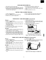
Page 23: ...ps on the cavity face plate 4 Lift entire case from the unit CAUTION DISCONNECT OVEN FROM POWER SUP PLY BEFORE REMOVING OUTER CASE POWER TRANSFORMER REMOVAL 1 CARRY OUT 3D CHECKS 2 Disconnect wire leads from power transformer magnetron and capacitor terminals 3 Remove four 4 screws holding transformer to base plate right 4 Remove transformer Re install 1 Rest transformer on the base cabinet with i...

Page 24: ...tall the fan motor to the fan motor angle with the two 2 screws 2 Install the fan blade to the fan motor shaft according the following procedure 1 Hold the centre of the bracket which supports the shaft of the fan motor on the flat table 2 Apply the screw lock tight into the hole for shaft of the fan blade 3 Install the fan blade to the shaft of fan motor by pushing thefanbladewithasmall lightweig...

Page 25: ... for New Zealand 4 CARRY OUT 4R CHECKS Note Step 4 above is important and it must be done after replacing power supply cord Noise filter Power supply cord Brown wire Blue wire Green Yellow wire Figure C 2 b Power supply cord replacement Removal 1 CARRY OUT 3D CHECKS 2 Remove the one 1 screw holding the green yellow wire to the bottom cabinet 3 Disconnect the brown wire lead of the power supply cor...

Page 26: ...ck upper position of latch hook pushing and pulling upper portion of door toward the oven face Then check lower portion of the latch hook pushing and pulling lower portion of the door toward the oven face Both results play in the door should be less than 0 5mm 2 The 2nd latch switch and stop switch interrupt the circuit before the door can be opened 3 Monitor switch contacts close when door is ope...

Page 27: ... survey meter Refer to Microwave Measurement Procedure Note The door on a microwave oven is designed to act as an electronic seal preventing the leakage of microwave energy from oven cavity during cook cycle This function does not require that door be air tight moisture condensation tight or light tight Therefore occasional appearance of moisture light or sensing of gentle warm air movement around...

Page 28: ...crowave ovens must be used for testing Recommended instruments are NARDA 8100 NARDA 8200 HOLADAY HI 1500 SIMPSON 380M 2 Place the oven tray into the oven cavity 3 Place the load of 275 15ml of water initially at 20 5 C in the centre of the oven tray The water container should be a low form of 600 ml beaker with inside diameter of approx 8 5cm and made of an electrically non conductive material suc...

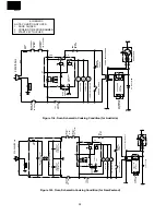
Page 29: ...ERMAL CUT OUT 145 C OVEN RY 2 2ND LATCH SWITCH MONITOR RESISTOR 0 8 20W POWER TRANSFORMER MAGNETRON H V RECTIFIER ASYMMETRIC RECTIFIER CAPACITOR 1 07µ AC2100V TURNTABLE MOTOR FAN MOTOR OVEN LAMP STOP SWITCH MONITOR SWITCH CONTROL UNIT THERMAL CUT OUT 145 MG THERMAL CUT OUT 95 C FAN 1ST LATCH SWITCH B1 B2 A5 A3 OL FM TTM N O RY 1 COM A1 THERMAL CUT OUT 145 C OVEN RY 2 2ND LATCH SWITCH MONITOR RESIS...

Page 30: ... M8A A1 THERMAL CUT OUT 145 C OVEN RY 2 2ND LATCH SWITCH MONITOR RESISTOR 0 8 20W POWER TRANSFORMER MAGNETRON H V RECTIFIER ASYMMETRIC RECTIFIER CAPACITOR 1 07µ AC2100V TURNTABLE MOTOR FAN MOTOR OVEN LAMP STOP SWITCH MONITOR SWITCH CONTROL UNIT THERMAL CUT OUT 145 MG THERMAL CUT OUT 95 C FAN 1ST LATCH SWITCH B1 B2 A5 A3 OL FM TTM N O RY 1 COM A1 THERMAL CUT OUT 145 C OVEN RY 2 2ND LATCH SWITCH MON...

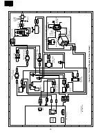
Page 31: ...VEN LAMP 2ND LATCH SWITCH GRN STOP SWITCH BLK WHT WHT WHT WHT GRY GRN GRY BLK BLK RED BLK GRY GRY BLK WHT BLK BLU WHT RED G Y BLK BLK GRY 1 GRN 2 GRN GRN 4 5 2 GRY 3 ORG 1 B R N BLK RED RED THERMAL CUT OUT 145 OVEN THERMAL CUT OUT 145 MG FAN MOTOR H V RECTIFIER HIGH VOLTAGE CAPACITOR EARTH LIVE FUSE M8A THERMAL CUT OUT 95 FAN MONITOR RESISTOR CN A CN B CN B RY3 COM NO CN A 1 2 1 3 5 RY1 TRANS FORM...

Page 32: ...VEN LAMP 2ND LATCH SWITCH GRN STOP SWITCH BLK WHT WHT WHT WHT GRY GRN GRY BLK BLK RED BLK GRY GRY BLK WHT BLK BLK BLK GRY 1 GRN 2 GRN GRN 4 5 2 GRY 3 ORG 1 BLK RED RED THERMAL CUT OUT 145 OVEN THERMAL CUT OUT 145 MG FAN MOTOR H V RECTIFIER HIGH VOLTAGE CAPACITOR THERMAL CUT OUT 95 FAN MONITOR RESISTOR CN A CN B CN B COM NO CN A 1 2 1 3 5 RY1 TRANS FORMER CONTROL UNIT Positive Lock N0 case Type 2 3...

Page 33: ...43ES R3 1K 1 2W R7 330 C4 R5 15K Q1 2SA933 R4 1K ZD2 HZ4C 3 C5 R40 3 3K SP 40 R41 1K F 1 F 1 P 1 P 2 F 2 F 2 1 G P 3 P 4 P 5 P 6 P 7 P 8 P 9 P 10 P 11 P 12 P 13 2 G 3 G 4 G 5 G 1 22 2 3 4 5 6 7 8 9 10 11 12 13 14 15 16 17 18 19 20 FLUORESCENT DISPLAY TUBE R23 R22 R21 R20 R13 R12 R11 R10 R83 R82 R81 R80 D8 D7 D6 D5 42 BUZZ D2 D1 INTO Vdisp R00 R01 R02 R03 TEST RESET OSC1 OSC2 GND AVSS AN0 AN1 AN2 A...

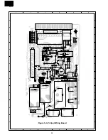
Page 34: ...0 15 21 IC 1 C 4 R60 CF1 R5 C5 R4 C3 ZD2 J6 2 J5 R3 D57 R7 4 R31 R40 SP40 R30 RB R2 1 D1 ZD3 C2 Q23 C20 B E B E B E Q22 J13 Q20 R20 B E D20 C21 Q21 D21 D22 R1 ZD1 VRS2 VRS1 J1 CN A POWER 5 1 RY1 6 J7 J9 J10 J8 R41 R11 C10 J12 R9 C30 D30 D23 DOOR SW CN B 2 3 1 E B Q1 R10 J11 F1 C1 E B Q2 J4 R6 5 CR50 CN G 10 12 5 1 1 P S1 S2 2 RY2 T1 RY3 J2 3 4 5 6 J3 DIP ...

Page 35: ...0 uF 35V 1 AC C3 VCEAB31CW476M Capacitor 47 uF 16V 1 AA C4 5 VCKYD11CY103N Capacitor 0 01 uF 16V 2 AH C10 VCTYF31HF103Z Capacitor 0 01 uF 50V 1 AB C20 VCEAB31HW104M Capacitor 0 1 uF 50V 1 AM C21 VCEAB31VW475M Capacitor 4 7 uF 35V 1 AA C30 VCKYD11CY103N Capacitor 0 01 uF 16V 1 AH CF1 RCRS A012DRE0 Ceramic resonator CST4 00MGW 1 AD CR50 RMPTEA011DRE0 CR array 1 AL D1 RSRCDA013DRE0 Diode bridge S1NB1...

Page 36: ...F 4 24 PCUSGA339WRP0 Cushion 1 AG 4 25 PPACGA084WRF0 Turntable motor packing 1 AF 4 26 LANGQA368WRP0 Fuse angle for Australia 1 AL 4 27 PCLIC0026WRE0 P clip 1 AA DOOR PARTS 5 DDORFA670WRK0 Door assembly complete 1 BL 5 1 FDORFA258WRT0 Door panel 1 BD 5 2 GCOVHA300WRF0 Choke cover 1 AN 5 3 FWAKPA060WRK0 Door frame assembly 1 AZ 5 4 LSTPPA120WRF0 Latch head 1 AM 5 5 MSPRTA081WRE0 Latch spring 1 AA 5...

Page 37: ...our order filled prompty and correctly please furnish the following information 1 MODEL NUMBER 2 REF NO 3 PART NO 4 DESCRIPTION 7 7 LX CZA038WRE0 Special screw 2 AA 7 8 LX CZ0052WRE0 Special screw 4 AA 7 9 XFPSD30P06000 Screw 3mm x 6mm 2 AA 7 10 XFPSD40P06000 Screw 4mm x 6mm 3 AA 7 11 LX CZA029WRE0 Special screw 3 AA 7 12 XFPSD40P08000 Screw 4mm x 8mm 4 AA 7 13 XHTSD40P08000 Screw 4mm x 8mm 1 AA ...

Page 38: ...13 1 12 4 23 1 4 4 20 7 8 4 13 4 14 4 16 7 1 4 18 4 9 7 1 7 8 7 2 7 8 1 1 1 1 1 1 1 2 4 1 1 4 7 9 4 5 7 2 7 1 7 6 4 3 7 1 7 10 7 1 6 8 1 6 7 2 1 5 4 11 7 1 4 4 7 9 1 8 1 7 1 16 4 19 7 2 4 24 4 15 7 1 7 5 7 5 4 10 7 3 1 15 4 17 7 5 4 8 7 11 4 10 7 10 1 14 4 25 4 6 2 1 7 1 6 9 1 10 7 2 1 11 7 13 1 10 7 4 4 26 1 17 For New Zealand For Australia 4 2 4 27 6 10 ...

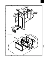
Page 39: ...37 R 3A56 6 4 5 1 2 3 6 4 5 1 2 3 A B C D E F G H A B C D E F G H CONTROL PANEL PARTS 3 2 3 1 3 3 3 4 3 5 3 1E 6 11 3 2 1 5 5 3 5 1 5 2 5 5 5 6 5 4 5 7 5 7 5 7 5 7 DOOR PARTS ...

Page 40: ...A257WRE0 Actual wire harness may be different than illustration 6 6 6 2 6 1 6 7 INTO THE OVEN CAVITY 6 8 6 5 6 12 Not replaceable items PACKING CASE DOOR PROTECTION SHEET SPADPA204WRE0 MICROWAVE OVEN PACKING PAD KIT CPADBA162WRK0 POLYETHYLENG BAG SSAKHA034WRE0 DOOR PAD SPADFA061WRE0 SPAKCC392WRE0 Australia Model SPAKCC397WRE0 New Zealand Model 6 13 PACKING AND ACCESSORIES MISCELLANEOUS ...

Reviews: