23
R-3A56
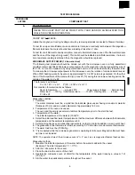
TURNTABLE MOTOR REMOVAL
1. Disconnect oven from power supply.
2. Remove turntable and turntable support from oven cavity.
3. Remove two (2) screws holding turntable motor cover to
base plates oven cavity and remove turntable motor
cover from bottom plate (right).
4. Disconnect wire leads from turntable motor.
(See "Positive lock connector removal")
5. Remove two (2) screws holding turntable motor to oven
cavity.
6. Now the turntable motor is free.
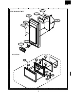
CONTROL PANEL ASSEMBLY REMOVAL
1. CARRY OUT 3D CHECKS
2. Disconnect wire leads from panel components.
3. Remove one (1) screw from upper side.
4. Remove control panel assembly and slide upward.
5. Now, individual components can be removed.
Removal
1. CARRY OUT 3D CHECKS.
2. Disconnect the brown and blue wires of the power supply
cord from the noise filter.
3. Remove the single (1) screw holding the earth wire of
power supply cord.
4. Remove the power supply cord from the rear cabinet.
Re-install
1. Insert the power supply cord into the oven cavity back
plate.
2. Connect the brown and blue wires of power supply cord
into the terminals of noise filter, referring to pictorial
diagram.
3. Re-install the earth wire to bottom plate with one (1)
screw.
POWER SUPPLY CORD REPLACEMENT (for New Zealand)
4. CARRY OUT 4R CHECKS.
Note : Step 4 above is important, and it must be done
after replacing power supply cord.
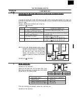
Noise filter
Power supply cord
Brown wire
Blue wire
Green/Yellow wire
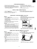
Figure C-2(b). Power supply cord replacement
Removal
1. CARRY OUT 3D CHECKS.
2. Remove the one (1) screw holding the green/yellow wire
to the bottom cabinet.
3. Disconnect the brown wire lead of the power supply cord
from the fuse holder.
4. Cut away the connector.
5. Release the power supply cord from the rear cabinet.
6. Now, the power supply cord is free.
Re-install
1. Insert the moulding cord stopper of power supply cord
into the square hole of the rear cabinet.
2. Install the earth wire lead of power supply cord to the
bottom plate with one (1) screw and tight the screw.
3. Connect the brown wire lead of power supply cord to the
fuse holder correctly, referring to the Pictorial Diagram.
4. Strip the blue wire lead of the power supply cord for
POWER SUPPLY CORD REPLACEMENT (for Australia)
15mm lengh from its end.
5. Wind the conductor of the blue wire lead of the power
supply cord and the conductor of the wire lead of the
main wire harness each other.
6. Insert them into the connector. And clamp it.
7. CARRY OUT 4R CHECKS.
15 mm
Connector
CE-230
Blue wire lead of power supply cord
Wire lead of the
main wire harness
Conductor:
Stripped portion
Connector
CE-230
Figure C-2(a). Power supply cord replacement
Summary of Contents for R-3A56
Page 2: ...R 3A56 ...

