background image

R343M - 17

Note: The parts marked '  

  ' have voltages in excess of 250V.

The parts marked '  

  ' may cause undue microwave exposure when damaged, loosened or removed.

   ' 

§'

    'mark : Spare part delivery section.

PART LIST

*

*

*

*

*

*

*

*

CABINET PARTS

CONTROL PANEL PARTS

REF NO

PART NO

§

DESCRIPTION                                              Q'TY     CODE

 3- 1

DPWBFB852WRK0

U   Control unit

1

BL

 3- 1A

QCNCMA430DRE0

U   3-pin connector (CN-A)

1

AC

 3- 1B

QCNCMA414DRE0      U   2-pin connector (CN-B)

1

AB

 3- 1C

FW-VZA218DRE0      U   4P harness (WH-1)

1

AE

 3- 1D

RLCDSA036DRE0      U   Liquid crystal display

1

AP

 3- 1E

LHLD-A179WRF0      U   LED holder

1

AE

 3- 1F

PSHEPA601WRE0      U   LED sheet

1

AD

 C1

VCEAB31VW227M

U   Capacitor     220 uF    16V

1

AB

 C10

RC-KZA087DRE0

U    Capacitor    0.01 uF    16V

1

AB

 C20

VCEAB31VW227M

U   Capacitor     220 uF    35V

1

AB

 C21

VCEAB31VW106M

U   Capacitor      10 uF    35V

1

AB

 C22

VCEAB31HW104M

U   Capacitor     0.1 uF    50V

1

AM

 C40

RC-KZA087DRE0

U   Capacitor     0.1 uF    50V

1

AB

 C41

VCEAB31CW476M

U   Capacitor      47 uF    16V

1

AA

 C42

RC-KZA087DRE0

U   Capacitor     0.1 uF    50V

1

AB

 C43-44

VCKYD11CY103N

U   Capacitor    0.01 uF    16V

2

AB

 C50

VCCCF61HH330J

U   Capacitor      33 pF    50V

1

AB

 C70

VCEAB31VW476M

U   Capacitor      47 uF    35V

1

AB

 C71

VCEAB31VW107M

U   Capacitor     100 uF    35V

1

AB

 C80

VCKYD11CY103N

U   Capacitor    0.01 uF    16V

1

AA

VCKYF31HF331N

U

Capacitor     330 uF    50V

1

AA

D1-3

VHD1N4005E61B

U   Diode (11ES1)

3

AE

 D10

VHD1SS270A/-1

U   Diode (1SS270ATA)

1

AA

 D20

VHD1SS270A/-1

U   Diode (1SS270ATA)

1

AA

 D70-71

VHD1N4005E61B

U   Diode (1N4005E)

2

AE

 D72-74

VHD1SS270A/-1

U   Diode (1SS270ATA)

3

AA

 D80

VHD1SS270A/-1

U   Diode (1SS270ATA)

1

AA

 IC1

RH-IZA919DRE0

U   LSI

1

AS

 LED1-3

VHPSLP7117E-3

U   Light emitting diode

3

AC

 Q20

VSKRA101M//-3

U   Transistor (KRA101M)

1

AA

 Q21

VSKRC105M//-3

U   Transistor (KRC105M)                          1

AB

 Q30

VSKRC101M//-3

U   Transistor (KRC101M)                          1

AA

 Q40

VS2SA1267Y/-3

U   Transistor (2SA1267Y)                         1

AC

 Q70

VSKRC105M//-3

U   Transistor (KRC105M)                          1

AB

ELECTRIC PARTS

REF NO

PART NO

§

DESCRIPTION                                              Q'TY     CODE

1-1

FH-DZA035WRE0

U

H.V. rectifier assembly

1

AP

1-2

FPWBFA308WRE2

U

Noise filter

1

AQ

1-3

QACCBA032WRE3

U

Power supply cord

1

AR

SW3

QSW-MA131WRE0

U

Stop switch

1

AK

MG

RV-MZA264WRE0

U

Magnetron

1

BK

C

RC-QZA238WRE0

U

High voltage capacitor

1

AR

SW1

QSW-MA131WRE0

U

Monitored latch switch

1

AK

SW2

QSW-MA133WRE0

U

Monitor switch

1

AN

FM

RMOTEA361WRE0

U

Fan motor

1

AT

F2

QFS-CA025WRE0

U

Fuse F8A

1

AC

OL

RLMPTA066WRE0

U

Oven lamp

1

AK

TTM

RMOTDA227WRE0

U

Turntable motor

1

AU

TC1

RTHM-A098WRE0

U

Thermal cut-out 125

°

C (Magnetron)

1

AH

TC2

RTHM-A098WRE0

U

Thermal cut-out 125

°

C (Oven)

1

AH

T

RTRN-A016URE1

U

Power transformer

1

BE

REF NO

PART NO

§

DESCRIPTION                                              Q'TY     CODE

2-1

GCABUA024URP0

U

Outcase cabinet (SL)

1

AX

2-1

GCABUA469WRT0

U

Outer case cabinet (W)

1

AX

2-1

GCABUA005URP0

U

Outercase cabinet (G)

1

AX

2-2

GDAI-A219WRP5

U

Base plate assembly

1

AS

2-3

GLEGPA028WRE0

U

Foot

4

AA

Summary of Contents for R-343GM

Page 1: ...SEMBLY 8 COMPONENT PLACEMENT AND ADJUSTMENT 12 WIRING RE WIRING 13 SCHEMATIC DIAGRAM 14 CONTROL PANEL CIRCUIT DIAGRAM 15 PRINTED WIRING BOARD DIAGRAM 16 PART LIST 17 EXPLODED DIAGRAM OF OVEN PARTS 20 CONTROL PANEL DOOR PARTS 21 MISCELLANEOUS PACKING ACCESSORIES 22 MODEL R 343 W M R 343 G M R 343 SL M SERVICEMANUAL R 343 10min 1min 10sec Poultry Meat Joint 8 7 1 Roast Beef Lamb 2 Roast Pork 3 Roast...

Page 2: ... completed and the oven is fully assembled the microwave power output should be checked and microwave leakage test carried out IMPORTANT If the oven becomes inoperative because of a blown fuse F8A in the 1st latch switch monitor switch circuit check the 1st latch switch and monitor switch before replacing the fuse F8A Sharp recommend that wherever possible fault finding is carried out with the sup...

Page 3: ...EEN AND YELLOW EARTH BLUE NEUTRAL BROWN LIVE If the mains lead is replaced only part number QACCBA032WRE3 should be used SPECIFICATION Power Requirements 230 240 Volts 50 Hertz Single phase 3 wire earthed Power Consumption 1 45kW Power Output 900 watts nominal of RF microwave energy Operating frequency of 2450 MHz Case Dimensions Width 520 mm Height 305 mm including foot Depth 413 mm Cooking Cavit...

Page 4: ...condition The circuits to the power transformer oven lamp fan motorandturntablemotorarecutoffwhenthemonitored latch switch and stop switch are made open Shown in the display is the remaining time 6 MONITOR SWITCH CIRCUIT The monitor switch SW2 is mechanically controlled by oven door and monitors the operation of the monitored latch switch SW1 6 1 When the oven door is opened during or after the cy...

Page 5: ...utine performance checks Note The following test method gives an indication of the output power only it cannot be used to establish the actual rated output power If the true output power is required then the IEC 60705 test method must be used Alternative simplified method 1 Place 2 litres of cold water between 12 C and 20 C in a suitable container 2 Stir the water and measure the temperature in C ...

Page 6: ... a short circuit If improper operation is indicated the tact switch is probably defective and should be checked B TACT SWITCH TEST The touch control panel consists of circuits including semiconductors such as LSI ICs etc Therefore unlike conventional microwave ovens proper maintenance can not be performed with only a voltmeter and ohmmeter In this service manual the touch control panel assembly is...

Page 7: ...age and oven power cord No 5 of the 3 pin connector A and the common terminal of the relay RY2 2 Only pattern at a is broken Insert jumper wire J1 and solder 3 Pattern at a and b are broken Insert the coil RCILF2003YAZZ between c and d NOTE At the time of making these repairs make a visual inspection of the varistor Check for burned damage If any abnormal condition is detected replace the defectiv...

Page 8: ...nel circuit The principal functions of these circuits and their related signals are explained below Tact Switch Signals generated in the LSI are sent to the tact switches through R60 R61 R62 and R63 When a tact switch is touched a signal is completed through the tact switch and passed back to the LSI through R81 to perform the function that was requested Control Unit Control unit consists of LSI A...

Page 9: ...witch SW2 or the tact switch SW6 is touched 16 R63 OUT Tact switch strobe signal Signal applied to tact switch section A pulse signal is input to R81 terminal while the tact switch SW1 is touched 17 AIN0 IN To input signal which communicates the door open close information to LSI Door close L level signal 0V Door open H level 5V 18 20 AIN1 AIN3 IN Terminal to change functions according to the Mode...

Page 10: ...terminal Signal is input to reset the LSI to the initial state when power is supplied Temporarily set L level the moment power is supplied at this time the LSI is reset Thereafter set at H level 36 HOLD IN OUT Connected to VDD 37 VLC IN Signal synchronized with commercial power source frequency Signal similar to VSS 38 COM1 OUT Common data signal COM1 Connected to LCD Pin No 1 39 COM2 OUT Common d...

Page 11: ...ransistor 2SA1267Y KRA101M KRC101M KRC105M B On some models the power supply cord between the touch control panel and the oven proper is so long enough that they may be separated from each other For those models therefore it is possible to check and repair the controls of the touch control panel while keeping it apart from the oven proper in this case you must short both ends of the door sensing s...

Page 12: ...H MONITORED SWITCH AND STOP SWITCH REMOVAL REMOVAL 1 CARRY OUT 3D CHECKS 2 Push the open button and open the door slightly 3 Insert a putty knife thickness of about 0 5mm into the gap between the choke cover and door frame as shown in Figure C 5 to free engaging parts 4 Release choke cover from door panel 5 Now choke cover is free CHOKE COVER PUTTY KNIFE DOOR FRAME MONITOR SWITCH STOP SWITCH MONIT...

Page 13: ...rame 4 Re install door panel to door frame by fitting eight 8 tabs of door frame to eight 8 holes of door panel 5 Fit the door panel to the door frame with four 4 screws 6 Insert two 2 pins of door panel on two 2 hole of upper and lower oven hinges 7 Re install choke cover to door panel Note After any service to the door Make sure that door sensing switch and primary latch switch are operating pro...

Page 14: ...NDICATES PARTS WITH POTENTIALS OVER 240V 230 240V 50Hz OVEN EARTH N L BLU BRN 17 17 G Y 17 MAGNETRON RECTIFIER POWER TRANSFORMER H V CAPACITOR 1 0 F 2100VAC FUSE F8A NOISE SUPPRESSION COIL 0 22 250V 0 0033 250V 0 0033 250V F1 680K 0 5W 10M 0 5W THERMAL 1250 C MAGNETRON FM OL M T T CUT OUT THERMAL RY2 RY1 MONITOR SWITCH A3 A1 A5 NO COM B1 B2 SW2 SW3 MONITORED LATCH SWITCH SW1 1250 C CUT OUT ...

Page 15: ... C3 C2 C1 22 25 30 35 40 42 21 1 5 10 15 R71 R72 R73 R81 R83 R90 R92 XIN XOUT RESET HOLD VLC COM1 COM2 COM3 COM4 VDD R91 INT2 INT1 AIN3 AIN2 AIN1 AIN0 R63 R62 R61 R60 J5 J7 R31 15k R64 100k R42 10kF R50 1k R41 1 5k 1 2w R40 ZD21 ZD20 ZD1 HZ12C1 HZ12C1 HZ12C1 C70 47µ 35v C20 220µ 35v C1 220µ 16v C71 100µ 35v C22 0 1µ 50v IC1 IZA919DR Auto Cook Defrost Power Level Weigft Stop Clear Start Auto Minute...

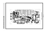
Page 16: ...D3 CN A J1 C21 C70 R42 R43 R40 R20 R72 4 5 6 R11 R41 B B 1 E B B E E E B C B A E R30 R31 R12 R10 R5 R4 R3 R2 R73 RY1 D73 R1 D1 VRS1 AC LINE VOLTAGE IS SUPPLIED TO ALL PARTS C10 C80 D80 ZD21 ZD20 D72 ZD70 D71 R81 C22 C20 Q70 C71 D10 ZD40 ZD1 DIP WARNING WARNING TRANSLESS SP30 IC1 F SW1 SW2 SW3 SW4 WH 1 SW5 SW6 SW7 SW60 CN B C60 C61 R64 R65 3 CF1 1 21 22 42 2 D2 C1 PRINTED WIRING BOARD DIAGRAM ...

Page 17: ...1ES1 3 AE D10 VHD1SS270A 1 U Diode 1SS270ATA 1 AA D20 VHD1SS270A 1 U Diode 1SS270ATA 1 AA D70 71 VHD1N4005E61B U Diode 1N4005E 2 AE D72 74 VHD1SS270A 1 U Diode 1SS270ATA 3 AA D80 VHD1SS270A 1 U Diode 1SS270ATA 1 AA IC1 RH IZA919DRE0 U LSI 1 AS LED1 3 VHPSLP7117E 3 U Light emitting diode 3 AC Q20 VSKRA101M 3 U Transistor KRA101M 1 AA Q21 VSKRC105M 3 U Transistor KRC105M 1 AB Q30 VSKRC101M 3 U Trans...

Page 18: ...EPA041URE0 U Key sheet R 343 W M 1 AL 3 2 1 PSHEPA042URE0 U Key sheet R 343 G M 1 AM 3 2 1 PSHEPA044URE0 U Key sheet R 343 SL M 1 AM 3 2 2 GMADIA006URF0 U Display window 1 AF 3 2 3 GCOVHA014URF0 U Key fixing frame 1 AL 3 3 HPNLCA028URF0 U Control panel frame R 343 W M 1 AN 3 3 HPNLCA030URF0 U Control panel frame R 343 G M 1 AN 3 3 HPNLCS004URR0 U Control panel frame R 343 SL M 1 AN 3 4 JBTN A017UR...

Page 19: ...b assembly 1 AW 5 9 XEBSD30P06000 U Screw 3mm x 6mm 6 AA 5 10 LSTPPA003URF0 U Glass stopper 1 AB MISCELLANEOUS REF NO PART NO DESCRIPTION Q TY CODE 6 1 FROLPA002URK0 U Roller stay 1 AM 6 2 NTNT A051WRE0 U Turntable tray 1 AN 6 3 TINS A191URR0 U Instruction book 1 AS 6 5 QW QZA210WRE1 U H V wire B 1 AD 6 6 FW VZA020URE1 U Main wire harness 1 AU 6 7 TCAUHA001WRR1 U Caution label 1 AC SCREWS NUTS AND...

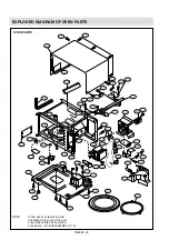
Page 20: ...MG 4 4 4 3 7 5 SW2 SW1 C 4 2 SW3 1 1 7 2 6 1 6 2 7 5 4 14 4 9 T 7 8 7 11 4 15 2 2 2 3 7 5 4 23 OL 6 8 7 9 7 5 TC1 7 7 7 9 F2 7 12 1 2 7 2 1 3 4 6 1 3 4 5 FM 7 3 7 5 x 4 6 14 x2 7 5 7 5 7 1 7 2 NOTE In the event of removing the turntable motor cover this part should be refitted using screw connection LX EZA045WRE0 7 10 ...

Page 21: ...R343M 21 CONTROL PANEL PARTS 5 9 5 9 5 4 5 3 5 1 5 8 5 2 5 5 5 6 5 7 5 10 3 2 1 3 2 2 3 2 3 3 1D 3 1F 3 1C 3 1E 3 3 3 4 3 5 3 1 3 6 3 6 CONTROL PANEL DOOR PARTS DOOR PARTS ...

Page 22: ...E OVEN TOP PACKING FPADBA233WRK1 BOTTOM PACKING FPADBA234WRK3 POLYETHENE BAG SSAKHA047WRE0 SPAKCA354URR0 W SPAKCA353URR0 G SPAKCA410URR0 SL ROLLER STAY TRAY HOLDER SPADPA015WRE0 TURNTABLE TRAY COOK BOOK INSTRUCTION BOOK MISCELLANOUS PACKING ACCESSORIES 6 5 TO MG TO HVC Actual wire harness may be different than illustration 6 6 ...

Page 23: ...R343M 23 NOTES ...

Page 24: ...R343M 24 Sharp Corp 2000 Printed in UK ...

Reviews: