background image

3

R - 2 2 A T
R-23AM
R - 2 4 A T

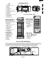
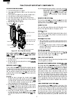
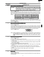
APPEARANCE VIEW

OVEN

1. Control panel
2. Hole for safety door latches
3. Ceramic floor
4. Splash cover
5. Oven light
6. Air intake filter
7. Air intake openings
8. Oven cavity
9. Door seals and sealing surfaces
10. Door hinges
11. Oven door with see-through window
12. Door safety latches
13. Door handle.
14. Outer cabinet
15. Removable cover over oven light bulb
16. Air vent openings
17.  Power supply cord
18 Mounting plate
19 Screw for mounting plate

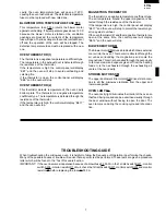
DISPLAY AND INDICATORS
for R-22AT  and R-24AT
Check indicators after the oven
starts to confirm the oven is oper-
ating as desired.

1. Heating indicator

This indicator shows cooking in
progress.

2. Memory number indicator
3. Express defrost
4. Check mode indicator
5. Power level display
6. Time display
7. Filter indicator
8. Double quantity mode indicator
9. 3rd. stage indicator
10. 2nd. stage indicator
11. 1st. stage indicator

OPERATING KEYS

12. DOUBLE QUANTITY key
13. EXPRESS DEFROST key
14. NUMBER keys
15. MANUAL/ REPEAT key
16. STOP/CLEAR key
17. POWER SLEVEL key
18. START key
19. SET key
20. VOLUME key
21. CHECK key

AUTO TOUCH CONTROL PANEL

INSTALLATION INFORMATION

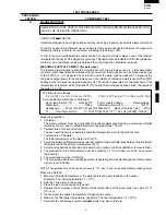
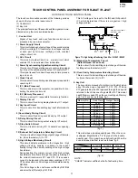
When this commercial  microwave oven is installed near other commercial electrical appliances, connect a lead wire to
each equivalent potential terminal with equipotential marking between them (insert a lead wire between a washer and
an earth angle, and screw them), as shown in Fig. A-1, to make sure that they are at equivalent potential.
If any lead wire is not connected between them, when person touch them he/she will get a electric shock.

COMMERCIAL MICROWAVE OVEN

OTHER COMMERCIAL 
ELECTRICAL APPLIANCE

Lead wire

Equipotential marking

Earth angle
(Equivalent potential terminal)

Equivalent 
potential terminal

Screw

Washer

Lead wire

Figure A-1

DISPLAY AND INDI-
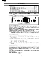
CATORS for R-23AM
Check indicators after
the oven starts to con-
firm the oven is operat-
ing as desired.

1. Cook indicator

This indicator shows
cooking in progress.

2. Time display
3. Microwave power level

display

OPERATING KEYS

4. HIGH

100%

5. MEDIUM

50%

6. MED LOW 20%
7. DEFROST 10%
8. TIME CONTROL

Rotate the control to en-
ter cooking time.

9. START button

MICROWAVE
POWER LEVEL
buttons

4

1

5

2

10

3

6

7

9

8

11

12

13

17

16

14

15

19

18

START

HIGH

MEDIUM

MED LOW

DEFROST

TIME 
CONTROL

4

5

6

7

8

9

POWER

%

ON

2
1

3

DEF CHECK

POWER

%

DOUBLE

ON

NUMBER

1

2

3

16

18

20

13

5

2
1

12

15

17

19

21

11

10

FILTER

3 4

6

7
8
9

1

2

3

4

5

6

7

8

9

0

11

12

13

14

15

16

17

18

19

20

14

EXPRESS
DEFROST

MANUAL/

REHEAT

STOP / CLEAR

POWER LEVEL

START

SET

CHECK

VOLUME

DOUBLE

QUANTITY

Summary of Contents for R-22AT

Page 1: ... WARNING 1 PRODUCT SPECIFICATIONS 2 GENERAL INFORMATION 2 APPEARANCE VIEW 3 OPERATION SEQUENCE 4 FUNCTION OF IMPORTANT COMPONENTS 6 TROUBLESHOOTING GUIDE 7 TEST PROCEDURE 9 TOUCH CONTROL PANEL ASSEMBLY 18 COMPONENT REPLACEMENT AND ADJUSTMENT PROCEDURE 28 MICROWAVE MEASUREMENT 35 WIRING DIAGRAM 36 PICTORIAL DIAGRAM 38 CONTROL PANEL CIRCUIT 39 PRINTED WIRING BOARD 42 PARTS LIST 44 1900W R 24AT 1 2 3...

Page 2: ...reconnect the leads to the primary of the power transformer SERVICING WARNING TO SERVICE PERSONNEL Microwave ovens contain circuitry capable of producing very high voltage and current Contact with following parts will result in electrocution High voltage capacitors High voltage transformers Magnetrons High voltage rectifier assembly High voltage fuses High voltage harness REMEMBER TO CHECK 4R 1 Re...

Page 3: ...de or antenna while the device is energized WARNING Never operate the oven until the following points are ensured A The door is tightly closed B The door brackets and hinges are not defective C The door packing is not damaged D The door is not deformed or warped E There is not any other visible damage with the oven Servicing and repair work must be carried out only by trained service engineers All...

Page 4: ...he combination of cooking time and microwave power The oven can be programmed a series of up to 3 cookling stages The combination of microwave power and cooking time that can be input as folllows Cooking Sequence Micrwave power levelthat can be iused Cooking time that can be iused 1 Stage only 0 100 Max 30 minutes 0 40 all stages Max 30 minutes any stages Max 60 minutes for 2 stages 2 or 3 Stage M...

Page 5: ...nstalled near other commercial electrical appliances connect a lead wire to each equivalent potential terminal with equipotential marking between them insert a lead wire between a washer and an earth angle and screw them as shown in Fig A 1 to make sure that they are at equivalent potential If any lead wire is not connected between them when person touch them he she will get a electric shock COMME...

Page 6: ...d and the contacts of the 1st latch switch SW1 remain closed remains closed the fuse F2 F6 3A will blow because the monitor switch is closed and a short circuit is caused MICROWAVE VARIABLE COOKING for R 22AT and R 24AT When the microwave oven is preset for variable cooking Closing the door activates all door interlock switches 1st latch switch 2nd latch switch 3rd latch switch and stop switch IMP...

Page 7: ...needed for heat ing up the magnetron filament 48 sec ON Number key 44sec ON Number key 9 40 sec ON Number key 8 36 sec ON Number key 7 32 sec ON Number key 6 26 sec ON Number key 5 22 sec ON Number key 4 16 sec ON Number key 3 12 sec ON Number key 2 8 sec ON Number key 1 0 sec ON Number key 0 48 sec ON 100 26sec ON 50 12 sec ON 20 8 sec ON 10 T1 HIGH VOLTAGE TRANSFORMER H V RECTIFIER C1 H V CAPACI...

Page 8: ...A 250V blows due to the operation of the monitor switch SW4 NOISE FILTER The noise filter assembly prevents radio frequency inter ference that might flow back in the power circuit FUSE F1 F13A If the wire harness or electrical components make a short circuit this fuse F1 F13A blows to prevent an electric shock or fire hazard FUSE F2 F6 3A 250V 1 If the wire harness or electrical components are sho...

Page 9: ...sistance of the thermistor If the temperature is high the control panel will display EE17 and the oven will stop to protect the lower magn etron against overheat Iftheoventhermistor 2 andthemagnetronthermistorare open at the same time the control panel will display EE16 and the oven will stop BLOWER MOTOR BM The blower motor BM drives a blade which draws external cool air into the oven This cool a...

Page 10: ...t stop EE 16 Thermistor of MG and 2 are open EE 17 Magnetron temperature is high EE 8 Relay melt short Stirrer motors do not work MAGNETRON MG1 MAGNETRON MG2 HIGH VOLTAGE TRANSFORMER T1 HIGH VOLTAGE TRANSFORMER T2 H V RECTIFIER ASSEMBLY FOR MG1 H V RECTIFIER ASSEMBLY FOR MG2 H V WIRE HARNESS H V CAPACITOR C1 H V CAPACITOR C2 1ST LATCH SWITCH SW1 2ND LATCH SWITCH SW2 3RD LATCH SWITCH SW3 MONITOR SW...

Page 11: ...ssel are at ambient temperature prior to the start the test 3 Temperature of the water The initial temperature of the water is 10 1 C 4 Selecttheinitialandfinalwatertemperaturesothatthemaximumdifferencebetweenthefinalwater temperature and the ambient temperature is 5 C 5 Select stirring devices and measuring instruments in order to minimize addition or removal of heat 6 The graduation of the therm...

Page 12: ...s an indication of the output power only it cannot be used to establish the actual rated output power If the true output power is required then the IEC60705 test method must be used Alternative simplified method 1 Place 2 litres of cold water between 12 C and 20 C in a suitable container 2 Stir the water and measure the temperature in C Note temperature as T1 3 Place the container in the microwave...

Page 13: ... of the high voltage rectifier and note the reading obtained Reverse the meter leads and note this second reading The normal resistance is infinite in one direction and more than 100 kΩ in the other direction CARRY OUT 4R CHECKS NOTE FOR MEASUREMENT OF THE RESISTANCE OF THE RECTIFIER THE BATTERIES OF THE MEASURING INSTRUMENT MUST HAVE A VOLTAGE AT LEAST 6 VOLTS BE CAUSE OTHERWISE AN INFINITE RESIS...

Page 14: ...blown when the door is opened check the 1st latch switchSW1 monitor switch SW4 and monitor resistor R1 If the fuse F2 F6 3A is blown by incorrect door switching replace the defective switch s and the fuse F2 F6 3A CARRY OUT 4R CHECKS CAUTION Only replace fuse F2 F6 3A with the correct value replacement 1 CARRY OUT 3D CHECKS 2 A continuity check across the temperature fuse terminals should indicate...

Page 15: ...oftheoventhermistor 1 withanohmmeter Connecttheohmmeterleadstotheleadsofthethermistor Room Temp 59 F 15 C 68 F 20 C 77 F 25 C Resistance Approx 373 kΩ Approx 292 kΩ Approx 231 kΩ If the meter does not indicate above resistance replace the thermistor 2 3 OVEN THERMISTOR 2 TEST Disconnect the two connectors of the magnetron thermistor and oven thermistor 2 from the switch harness Measure the resista...

Page 16: ...FOR R 23AM The control panel consists of circuits including semiconductors such as LSI etc Therefore unlike conventional microwave ovens proper maintenance cannot be performed with only a voltmeter and ohmmeter In this service manual the touch control panel assembly is divided into three units Control Unit Switch Unit and Encoder Unit troubleshooting by unit replacement is described according to t...

Page 17: ... of the connector CN F as described in the following table by using ohmmeter when the switches are released and depressed 4 If incorrect readings are obtained replace the defective switch 5 CARRY OUT 4R CHECKS P KEY UNIT TEST FOR R 24AT R 22AT a When rotating the encoder the cooking time can not be entered 3 Control Unit The following symptoms may indicate a defective control unit Replacing the co...

Page 18: ...eplace the defective parts CARRY OUT 4R CHECKS TEST PROCEDURES PROCEDURE LETTER COMPONENT TEST Check voltage at the relay coil with a D C voltmeter during the microwave cooking operation DC voltage indicated Defective relay DC voltage not indicated Check diode which is connected to the relay coil If diode is good control unit is defective RELAY SYMBOL OPERATIONAL VOLTAGE CONNECTED COMPONENTS RY1 A...

Page 19: ...ltage T1 transformer to voltages required at each part by full wave rectifying circuit constant voltage circuit etc 2 ACL Circuit This is an Auto clear Circuit i e a reset circuit which enables IC1 to be activated from initial state 3 Power Synchronizing Signal Generating Circuit This is a circuit for generating power synchronizing signal by virtue of the secondary side output of transformer T1 Th...

Page 20: ...ransmitting output change of thermistor Oven thermistor 1 to IC1 12 High Voltage Monitoring Circuit This circuit detects problems in the magnetron high voltage circuit by sensing a variation in the current flowingthroughtheprimarywindingofthehighvoltage transformer During heating the primary current of the high voltage transformers also flows through the pri mary winding of the current transformer...

Page 21: ...100 power level operation L level during cooking H level otherwise In other power level operation 90 80 70 60 50 40 30 20 10 or 0 H and L level is repeated according to power level Power level ON OFF Power level ON OFF 100 48sec 0sec 40 22sec 26sec 90 44sec 4sec 30 16sec 32sec 80 40sec 8sec 20 12sec 36sec 70 36sec 12sec 10 8sec 40sec 60 32sec 16sec 0 0sec 48sec 50 26sec 22sec 15 P42 OUT Power supp...

Page 22: ...y matrix is touched a corresponding signal will be input into R1 37 R0 IN Signal similar to R3 When either one of G 9 line keys on key matrix is touched a corresponding signal will be input into R0 38 VP IN Anode segment of Fluorescent Display light up voltage 31V Vp voltage of power source circuit input 39 P17 OUT Segment data signal The relation between signals and indicators are as follows Sign...

Page 23: ...2 P21 Relationship of signal level combination to sound volume level is shown in the following table 1 3 in the table however are indicated in the descending order from the maximum level of sound volume through the minimum level Sound Volume P21 P22 1 Max L L 2 H L 3 Min L H At Output terminal P32 rectangular wave signal of 2 5kHz is output 61 P21 OUT Sound level control signal Refer to above sign...

Page 24: ... be input into P51 18 P50 IN Signal similar to P51 When either one of switches SW1 SW3 and SW5 on the switch unit is pressed a corresponding signal out of P43 P44 and P45 will be input into P50 19 P47 OUT Signal to sound buzzer This signal is to control the 2 5kHz continuous signal A Switch touch sound B Completion sound 20 P46 OUT Terminal not used 21 P45 OUT Switch strobe signal Signal is applie...

Page 25: ... relay In100 power level operation L level during cooking H level otherwise In other power level operation 50 20 or 10 H and L level is repeated according to power level P0WER LEVEL ON OFF 50 26sec 22sec 20 12sec 36sec 10 8sec 40sec 37 38 P23 P22 OUT Terminal not used 39 48 P21 P10 OUT Segment data signal The relation between signals and indicators are as follows Signal Segment Signal Segment P01 ...

Page 26: ...in No Signal I O Description 1 3 A0 A2 IN Connected to GND 4 VSS IN Connected to VC 5V 5 SDA IN OUT Serial data input output input outputs data to IC1 6 SCL IN Clock signal input input outputs serial data at every one pulse 7 TEST IN Connected to VC 5V 8 VCC IN Connected to GND A0 8 1 7 2 6 3 5 4 A1 A2 VSS VCC TEST SCL SDA TOP VIEW FUNCTIONAL DIAGRAM E PROM 512 x 8 2 START STOP LOGIC CONTROL LOGIC...

Page 27: ... its input and output termi nals For this reason it is easily influenced by the surrounding high voltage power source static electricity charge in clothes etc and sometimes it is not fully protected by the built in protection circuit In order to protect CMOS LSI 1 When storing and transporting thoroughly wrap them in aluminium foil Also wrap all PW boards containing them in aluminium foil 2 When s...

Page 28: ...S OF MICROWAVE OVEN FOR R 24AT R 22AT The following procedure enables the servicer to obtain the totalservicecounts cookcycles formemorycooking manual repeat double quantity cooking and defrost The maximum capacity of the counter is 999 999 counts above which the counterwillresetto 0 Thecounterwillretainthetotalcounts will not clear in the event of a power disruption 1 Practice for checking total ...

Page 29: ...2 8268 CHECK User s Total Counts 1 VOLUME 2 8268 CHECK VOLUME 2 8268 CHECK DOUBLE 3 xxxxxx CHECK QUANTITY Total Counts of Service 3 3030 CHECK SET 0 CHECK 2 2 3 5 2235 CHECK x4 SET 2235 CHECK CHECK 1 Denotestheprocedurefortheservicertodisableclearing This procedure is instructed to service personnel only and is excluded from the operation manual 2 If the IC 2 is exchanged 0 should be indicated ins...

Page 30: ...abinet and power supply cord 8 Remove the screws holding the rear cabinet to the oven cavity and blower motor 9 Remove the one 1 screws holding the switch mount ing angle to the rear cabinet and release the switch mounting angle from the rear cabinet 10 Disconnectthepowersupplycordfromthefuseholder 11 Remove the one 1 screws holding the grounding wire of power supply cord to the oven cavity 12 Rem...

Page 31: ...etron thermistor angle holding the magnetron thermistor 7 Remove the magnetron thermistor from the thermistor angle 8 Now the magnetron thermistor is free Re install 1 Install the magnetron thermistor to the thermistor angle as shown in Figure C 1 MAGNETRON THERMISTOR REPLACEMENT 1 CARRY OUT 3D CHECKS 2 Remove the rear cabinet too 3 Remove two 2 screws holding earth side terminals of high voltage ...

Page 32: ... connector is free CAUTION WHEN CONNECTING THE POSITIVE LOCK CONNECTORS TO THE TERMI NALS CONNECT THE POSITIVE LOCK CONNECTOR SO THAT THE LEVER FACES YOU Now the the high voltage rectifier assembly is free 8 Remove two 2 screws holding the capacitor holder to oven cavity Now the capacitors are free CAUTION 1 DISCHARGE THE TWO HIGH VOLTAGE CAPACI TORS BEFORE TOUCHING ANY OVEN COMPO NENTS OR WIRING ...

Page 33: ...or 2 Close covers of the terminal insulator as shown illustlated below B A C B Fig 1 Fig 2 TOUCH CONTROL PANEL SCREW DRIVER Flat type screw driver Terminal insulator RECEPTACLE COVERS Replacement of individual component is as follows for R 23AM CONTROLUNITANDCONTROLPANELFRAME WITH SWITCH UNIT 7 Remove two 2 screws holding the control panel mounting angle to the panel frame 8 Lift up the control pa...

Page 34: ...am 3 Install the green yellow wire of power supply cord with the one 1 screw 4 Re install the cord bushing to the rear cabinet 5 CARRY OUT 4R CHECKS 1 CARRY OUT 3D CHECKS 2 Remove the control panel from the oven cavity refer ring to CONTROL PANEL REMOVAL 3 Remove the two 2 screws holding the latch hook to the oven cavity 4 Open the door and pull the latch hook out of the oven cavity 5 For 3rd latc...

Page 35: ... by pulling it forward 4 Release upper and lower oven hinges from door as sembly 5 Now door assembly is free NOTE When individual parts are replaced refer to Door Disassembly RE INSTALL 1 Insert the upper and lower oven hinges into door hinge pins 2 Insert the upper and lower oven hinges with door assembly into rectangular holes of oven cavity front plate 3 Make sure that the door is parallel with...

Page 36: ...e DOOR HANDLE REMOVAL 1 Remove the door assembly from oven cavity RE MOVAL of DOOR REPLACEMENT AND ADJUST DOOR DISASSEMBLY UPPER OVEN HINGE LOWER OVEN HINGE CHOKE COVER DOOR HANDLE LATCH HEAD BENT 2 1 PUTTY KNIFE PUTTY KNIFE CHOKE COVER DOOR PANEL FRONT BENT MENT 2 Place door assembly on a soft cloth with latches facing up 3 Remove choke cover from door panel referring to CHOKE COVER REMOVAL 4 Rem...

Page 37: ...e gap b across the face of the door c across any vents in the oven s sides rear or top Dotted line indicates the path taken by the leakage detector WhilstthemaximumleakagepermittedinBSEN60335 2 25is50W m2 equivalentto5mW cm2 itisnotnormaltodetect any significant leakage and therefore any detected leakage should be investigated After any repair the microwave oven must be checked for microwave leaka...

Page 38: ...SE M8A SM UPPER STIRRER MOTOR LOWER STIRRER MOTOR SM BM B2 B3 H1 H3 MAGNETRON THERMISTER H V RECTIFIER C2 H V CAPACITOR MG2 MAGNETRON H V FUSE 0 6 A 5 kV R 22AT 0 75 A 5 kV R 24AT R 23AM T2 HIGH VOLTAGE TRANSFORMER L BLK WHT N OL RY1 EARTH H V FUSE 0 6 A 5 kV R 22AT 0 75 A 5 kV R 24AT R 23AM F1 FUSE F13A NOISE FILTER SW1 1ST LATCH SWITCH PRIMARY INTERLOCK SWITCH SW4 MONITOR SWITCH NOISE SUPPRESSIO...

Page 39: ...CH SWITCH F4 FUSE M8A A1 TF1 MAGNETRON 1 TEMP FUSE 150 C TF2 MAGNETRON 2 TEMP FUSE 150 C OVEN LAMP BLOWER MOTOR A3 CONTROL UNIT RY3 R 22AT 24AT RY2 R 23AM RY4 R 22AT 24AT RY3 R 23AM B1 SW3 3RD LATCH SWITCH OVEN THERMISTER 1 OVEN THERMISTER 2 SW5 STOP SWITCH TAB3 TAB2 TAB1 TAB4 T1 HIGH VOLTAGE TRANSFORMER H V RECTIFIER C1 H V CAPACITOR MG1 MAGNETRON F3 FUSE M8A SM UPPER STIRRER MOTOR LOWER STIRRER ...

Page 40: ...OCKET PNK OVEN THERMISTOR 1 TF2 MAGNETRON TEMP FUSE 150 C F2 FUSE F6 3A G Y POWER SUPPLY CORD EARTH NEUTRAL LIVE WHT PNK GRY SW4 MONITOR SWITCH BM BLOWER MOTOR CN D BLK ORG RED 1 GRN 3 BLK 2 ORG CN B GRN GRN WHT SW2 2ND LATCH SWITCH Oven side BLK RED ORG ORG ORG WHT WHT SM STIRRER MOTOR Upper YLW PNK WHT GRY BLK GRY PNK ORG PNK T2 HIGH VOLTAGE TRANSFORMER C1 HIGH VOLTAGE CAPACITOR H V RECTIFIER BL...

Page 41: ...M R20 15K C22 C20 Q81 DTD143ES C82 C81 1µF 50V 2 2µF 50V R80 470 Q80 DTA114YSA C80 0 1µF 50V R32 2 7K R33 10K J2 8 2K J3 36K RY1 D81 OVEN LAMP BLOWER MOTOR MICRO 1 MICRO 2 CT1 RY3 D83 RY4 D84 CT2 Q83 DTB143ES Q84 DTB143ES R61 2 0KF D61 D62 R62 2 0KF R65 300K R66 300K R63 1K R64 1K C62 22µF 25V D70 11ES1 C70 0 01µF 50V D71 R70 100 DOOR R71 30K C71 R73 33K R74 3 3K R72 1 1K THERMISTOR 1 STOP SWITCH ...

Page 42: ...KRA101M R20 15K C22 C20 Q81 DTD143ES C82 C81 1µF 50V 2 2µF 50V R80 470 Q80 DTA114YSA C80 0 1µF 50V R32 2 7K R33 10K J2 J3 RY1 D81 OVEN LAMP BLOWER MOTOR MICRO 1 MICRO 2 CT1 RY3 D83 RY4 D84 CT2 Q83 DTB143ES Q84 DTB143ES R61 2 0KF D61 D62 R62 2 0KF R65 300K R66 300K R63 1K R64 1K C62 22µF 25V D70 11ES1 C70 0 01µF 50V D71 R70 100 DOOR R71 30K C71 R73 33K R74 3 3K R72 1 1K THERMISTOR 1 STOP SWITCH IF ...

Page 43: ...T MEDIUM MED LOW HIGH SW UNIT R63 47K R37 47K R36 47K D32 D33 R51 5 1K 3 3K J4 J3 J2 J1 VA C60 0 01µ 25V MAGNETRON THERMISTOR STOP SWITCH OVEN THERMISTOR 1 OVEN THERMISTOR 2 H 3 H 1 B 1 B 2 B 3 Q70 KRA101M R70 3 3K SP1 D50 R50 100 C50 D20 11ES1 R40 1 1K R41 110K R42 3 3K IF NOT SPECIFIED 1SS270A IF NOT SPECIFIED 1 4W 5 IF NOT SPECIFIED 0 01µ 16V TAB4 TAB3 TAB2 TAB1 A 1 A 3 A 5 A 7 OVEN LAMP BLOWER...

Page 44: ...WER POWER P S2 S1 T1 C4 C3 J22 J10 Q85 Q84 Q83 Q80 C20 C85 J12 R85 J13 R83 R9 J30 J8 R43 R42 D200 Q40 D70 DOOR SW D61 R79 R74 D83 CT1 RY3 RY2 RY1 J24 R62 R66 D62 F1 J26 D7 D5 C8 C82 RY4 R8 R7 J28 D84 D6 Q81 E B C1 C81 C2 CT2 C9 TAB1 TAB2 R73 R33 R32 R67 R68 ZD1 R1 R21 C21 R31 C11 J14 C10 J18 R82 J20 R81 J15 C30 IC2 R3 R72 D201 E B Q201 B Q200 E R101 C74 ZD2 CF1 R5 C E B Q2 R100 R99 R96 R95 R94 R93...

Page 45: ...2 D33 4 7 8 10 R22 J22 9 B B B B B F1 16 J7 D23 D7 D6 C31 D31 R31 R33 D5 B B E E E E E E 5 C7 C5 C3 C4 ZD1 13 14 15 C11 C12 C2 12 C20 CF1 D60 R65 R61 J13 E E Q2 C6 B B J10 R80 R81 R82 R3 R4 ZD2 R83 Q60 1 C13 C14 IC1 C80 C81 6 J4 3 R85 R42 R63 R36 R37 D50 C50 CN B R50 R41 R40 R2 B Q1 R1 R70 R32 R30 D30 SP1 C8 C9 D4 1 4 5 6 7 3 2 P S2 S1 R23 J23 D2 D1 D3 R5 E 11 CT1 TAB2 TAB1 TAB3 TAB4 CT2 CN A RY2 ...

Page 46: ...ly 1 BC 2 2 PSHEGA006WRE0 Rubber sheet A 2 AF 2 3 PSHEGA007WRE0 Rubber sheet B 2 AE 2 4 GCOVAA283WRW0 Rear cabinet 1 AX 2 5 FFTASA064WRY0 Oven lamp access cover assembly 1 AN 2 5 1 PCUSU0407WRP0 Cushion 1 AA 2 5 2 PREFHA059WRP0 Reflector 1 AF 2 6 GCABUA523WRP0 Outer case cabinet 1 BA 2 7 FFPF A016WRK0 Vibration proof sheet 1 AU 2 8 PZETEA079WRP0 Insulation sheet 2 AC OVEN PARTS 4 1 PZETEA047WRP0 S...

Page 47: ...BDGCA091WRE0 Door badge R 24AT 1 AF 5 19 HBDGCA092WRE0 Door badge R 23AM 1 AF 5 19 HBDGCA094WRE0 Door badge R 22AT 1 AF 5 20 XEPSD40P20000 Screw 4mm x 20mm 2 AB 5 21 PCUSUA523WRP0 Door lever cushion 2 AE 5 22 PSPA A102WRE0 Door case spacer 2 AE MISCELLANEOUS 6 1 TINSEA821WRR0 Operation manual R 22AT R 24AT 1 AG 6 1 TINSEA822WRR0 Operation manual R 23AM 1 AG 6 2 TLABHA029WRR0 Menu sticker R 22AT R ...

Page 48: ...0mm 3 AA 7 21 LX WZA035WRE0 Special washer 2 AB 7 22 XOTWW40P08000 Screw 4mm x 8mm 7 AB 7 23 PSPA A101WRE0 Special washer 4 AB 7 24 XCPSD30P06000 Screw 3mm x 6mm 2 AA 7 25 LX BZA064WRE0 Special screw 1 AA 7 26 XOTSC40P12000 Screw 4mm x 12mm 5 AA 7 27 LX EZA042WRE0 Special screw 4 AB 7 28 XFTSD40P08000 Screw 4mm x 8mm 1 AA 7 29 XTPSD40P08000 Screw 4mm x 8mm 2 AA 7 30 XWWSD50 06000 Washer 5mm x 0 6m...

Page 49: ...18 4 26 4 26 6 6 7 18 7 16 7 14 7 16 7 14 7 16 7 16 7 16 7 2 7 3 7 27 7 8 7 8 4 41 7 17 7 16 7 17 7 5 7 27 7 30 7 10 7 16 7 19 7 15 7 15 7 30 4 26 7 18 7 31 x2 x2 7 22 2 2 x2 1 17 1 6 7 16 2 8 2 8 7 19 7 17 6 8 7 4 7 23 7 9 7 9 4 44 7 16 1 13 1 2 7 23 7 6 7 11 6 6 7 11 4 17 4 21 1 14 7 16 4 18 1 22 4 1 7 32 7 21 1 6 4 33 6 10 1 16 4 32 7 7 4 13 1 23 6 15 4 42 1 4 7 22 1 9 1 5 1 5 1 25 1 11 7 20 7 ...

Page 50: ...A B C D E F G H A B C D E F G H Actual wire harness may be different from illustration 6 7 6 4 6 16 6 14 6 3 5 15 5 16 5 17 5 18 5 4 5 11 5 11 5 20 5 12 5 10 5 22 5 14 5 1 5 9 5 8 5 7 5 6 5 13 5 13 5 2 5 3 5 21 5 5 5 19 5 6 5 MISCELLANEOUS DOOR PARTS ...

Page 51: ...e 1SS270A 1 AA D81 VHD1SS270A 1 Diode 1SS270A 1 AA D83 84 VHD1SS270A 1 Diode 1SS270A 2 AA D93 97 VHD1SS270A 1 Diode 1SS270A 5 AA IC1 RH IZA646DRE0 LSI 1 AX IC2 RH IZA571DRE0 IC AT24C04 1 AP Q1 VS2SB953 PQ 4 Transistor 2SB953 1 AG Q2 VS2SA933AS 3 Transistor 2SA933ASTP 1 AB Q20 RH TZA037CBE0 Transistor KRA101M 1 AA Q40 RH TZA037CBE0 Transistor KRA101M 1 AA Q41 VS2SB1238 3 Transistor 2SB1238 1 AA Q80...

Page 52: ...12C1 1 AA ZD2 VHEHZ4C3 1 Zener diode HZ4C3 1 AA 3 2 FPNLCB469WRK0 Control panel frame with key unit assembly 1 BA 3 2 1 FUNTKA964WRE0 Key unit 1 AW 3 2 2 HDECAA195WRP0 Decoration metal fittings 1 AP 3 2 3 PCUSUA451WRP0 Cushion 1 AB 3 3 LANGTA243WRW0 Control panel mounting angle 1 AF 3 4 XEPSD30P10XS0 Screw control unit mounting 6 AA 3 5 XEPSD40P12000 Screw control panel mounting angle mounting 1 A...

Page 53: ...A037CBE0 Transistor KRA101M 1 AA Q20 VSDTA114YSA 3 Transistor DTA114YSA 1 AB Q21 VSDTD143ES 3 Transistor DTD143ES 1 AC Q22 23 VSDTB143ES 3 Transistor DTB143ES 2 AC Q70 RH TZA037CBE0 Transistor KRA101M 1 AA R1 VRD B12EF182J Resistor 1 8k ohm 1 4W 1 AA R2 VRD B12HF561J Resistor 560 ohm 1 2W 1 AA R3 VRD B12EF102J Resistor 1 0k ohm 1 4W 1 AA R4 VRD B12EF153J Resistor 15k ohm 1 4W 1 AA R5 VRD B12HF150J...

Page 54: ...PWBFB195WRU0 Switch unit assembly 1 AP 3 12 1 FW VZA165DRE0 Lead wire harness 2 pin 1 AF 3 12 2 FW VZA166DRE0 Lead wire harness 5 pin 1 AH 3 12 3 QSW PA025DRE0 Tact switch SW1 SW5 5 AD 3 13 PCUSUA404WRP0 Select cushion 4 AC 3 14 PCUSGA401WRP0 Cushion 1 AD 3 15 MSPRPA082WRE0 Spring 1 AD 3 16 PCUSUA407WRP0 Water proof cushion B 1 AB 3 17 PCUSUA408WRP0 Water proof cushion C 1 AC 3 18 PCUSUA406WRP0 Wa...

Page 55: ...AT 6 4 5 1 2 3 6 4 5 1 2 3 A B C D E F G H A B C D E F G H CONTROL PANEL PARTS R 23AM 3 2 3 3 2 4 3 2 2 3 2 1 3 2 3 1 3 4 3 19 3 9 3 4 3 8 3 6 3 20 3 21 3 3 3 15 3 22 3 5 3 17 3 18 3 7 6 9 3 13 3 10 3 11 3 14 3 16 3 23 3 12 ...

Page 56: ...54 R 22AT R 23AM R 24AT 99SHARP CORP 11S0 520E Printed in Germany ...

Reviews: