background image

26

R-2110JK
R-2110JW
R-2120JK
R-2120JW

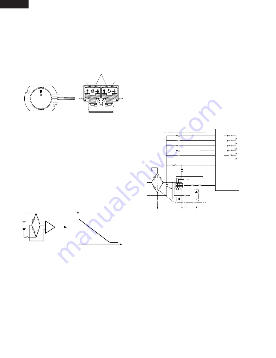
(1) Structure of Humidity Sensor

The humidity sensor includes two thermistors as shown
in the illustration. One thermistor is housed in the closed
vessel filled with dry air while another in the open vessel.
Each sensor is provided with the protective cover made
of metal mesh to be protected from the external airflow.

(2) Operational Principle of Humidity Sensor

The figure below shows the basic structure of a humidity
sensor. A bridge circuit is formed by two thermistors and
two resistors (R1 and R2).
The output of the bridge circuit is to be amplified by the
operational amplifier.
Each thermistor is supplied with a current to keep it
heated at about 150˚C (302˚F), the resultant heat is
dissipated in the air and if the two thermistors are placed
in different humidity conditions they show different
degrees of heat conductivity leading to a potential
difference between them causing an output voltage
from the bridge circuit, the intensity of which is increased
as the absolute humidity of the air increases. Since the
output is very minute, it is amplified by the operational
amplifier.

(3) Detector Circuit of Humidity Sensor Circuit

This detector circuit is used to detect the output voltage
of the humidity circuit to allow the LSI to control sensor
cooking of the unit.  When the unit is set in the sensor
cooking mode, 16 seconds clearing cycle occurs than
the detector circuit starts to function and the LSI observes
the initial voltage available at its AN1 terminal.
With this voltage given, the switches SW1 to SW5 in the
LSI are turned on in such a way as to change the
resistance values in parallel with R98 ~ R102. Changing
the resistance values results in that there is the same
potential at both F-3 terminal of the humidity sensor and
AN0 terminal of the LSI. The voltage of AN1 terminal will
indicate about -2.5V. This initial balancing is set up
about 16 seconds after the unit is put in the Sensor
Cooking mode.

HUMIDITY SENSOR CIRCUIT

As the sensor cooking proceeds, the food is heated to
generate moisture by which the resistance balance of
the bridge circuit is deviated to increase the voltage
available at AN1 terminal of the LSI.
Then the LSI observes that voltage at AN1 terminal and
compares it with its initial value, and when the comparison
rate reaches the preset value (fixed for each menu to be
cooked), the LSI causes the unit to stop sensor cooking;
thereafter, the unit goes in the next operation
automatically.
When the LSI starts to detect the initial voltage at AN1
terminal 16 seconds after the unit has been put in the
Sensor Cooking mode, if it is not possible to balance the
bridge circuit due to disconnection of the humidity
sensor, ERROR will appear on the display and the
cooking is stopped.

1) Humidity sensor circuit

ventilation opening for sensing

Sensing part
(Open vessel)

Sensing part
(Closed vessel)

Thermistors

C

S

R3

R1

R2

+

Operational
amplifier

Output
voltage

S : Thermistor
     open vessel

C : Thermistor
      closed vessel

2

Absolute humidity (g/m  )

Output voltage

Absolute humidity vs,
output voltage characteristic

SW1

SW2

SW3

SW4

SW5

P50

P51

P52

P53

P54

 LSI
(IC1)

AN0

AN1

620k

300k

150k

75k

37.4k

18

15

14

10

9

16

17

47k

47k

15k

1 2 3 4

8 7 6 5   

0.01uF

0.1uF

0.01uF

VA : -15V

VA : -15V

R90

C90

C91

C93

C92

S

F-2

1.8k

IC2

F-1

F-3

C

3.57k

3.32k

VC : -5V

0.1 uF

C. Thermistor in 
    closed vessel
S. Thermistor in
    open vessel

R98

R99

R96

R91

360k

R93

R92

R94

R95

D90

R100

R101

R102

R97

Summary of Contents for R-2110JK

Page 1: ...120JW OVER THE RANGE MICROWAVE OVEN MODELS SERVICE MANUAL SHARP CORPORATION This document has been published to be used for after sales service only The contents are subject to change without notice TABLE OF CONTENTS Page PRECAUTIONS TO BE OBSERVED BEFORE AND DURING SERVICING TO AVOID POSSIBLE EXPOSURE TO EXCESSIVE MICROWAVE ENERGY INSIDE FRONT COVER BEFORE SERVICING INSIDE FRONT COVER WARNING TO ...

Page 2: ...sion check as per the Microwave Measure ment Procedure outlined in this service manual If microwave emissions level is in excess of the specified limit contact SHARP ELECTRONICS CORPORATION immediately 1 800 237 4277 If the unit operates with the door open service person should 1 tell the user not to operate the oven and 2 contact SHARP ELECTRONICS CORPORATION and Food and Drug Administration s Ce...

Page 3: ...discharge high voltage capacitor wait for 60 seconds 4 Disconnect the leads to the primary of the inverter unit 5 Ensure that these leads remain isolated from other components and oven chassis by using insulation tape 6 After that procedure reconnect the power supply cord When the testing is completed 1 Disconnect the power supply cord and then remove outer case 2 Open the door and block it open 3...

Page 4: ...plastic The placing of this standard load in the oven is important not only to protect the oven but also to insure that any leakage is measured accurately 4 Set the cooking control on Full Power Cooking Mode 5 Close the door and select a cook cycle of several minutes If the water begins to boil before the survey is completed replace it with 275 ml of cool water C Leakage test Closed door leakage t...

Page 5: ...e door packing is not damaged D The door is not deformed or warped E There is no other visible damage with the oven Servicing and repair work must be carried out only by trained service personnel DANGER Certain initial parts are intentionally not grounded and present a risk of electrical shock only during servicing Service personnel Do not contact the following parts while the appliance is energiz...

Page 6: ... Full Power P 60 approx 60 of Full Power P 50 approx 50 of Full Power P 40 approx 40 of Full Power P 30 approx 30 of Full Power P 20 approx 20 of Full Power P 10 approx 10 of Full Power P 0 No power throughout the cooking time R 2110JK W KEEP WARM pad EASY DEFROST pad POPCORN pad SHORT CUTS pads QUICK BREAKFAST pad SNACK TIME pad DINNER FAVORITS pad TIMER CLOCK pad CUSTOM HELP pad Numer selection ...

Page 7: ...UMSTANCES CUT OR REMOVE THE GROUNDING PIN FROM THE PLUG The power supply cord and plug must be connected to a separate 120 Volt AC 60 Hz 15 Amp or more dedicated line using a grounded receptacle The receptacle should be located inside the cabinet directly above the Microwave Oven Hood system mounting location OVEN DIAGRAM 1 Oven door with see through window 2 Door hinges 3 Oven lamp It will light ...

Page 8: ...TE Some one touch cooking features such as MINUTE PLUS are disabled after three minutes when the oven is not in use These features are automatically enabled when the door is opened and closed or the STOP CLEAR pad is pressed R 2110JW R 2120JW ...

Page 9: ...e door was opened 7 The monitor switch is electrically monitoring the operation of the secondary interlock switch and primary interlock switch and is mechanically associated with the door so that it will function in the following sequence 1 When the door opens from a closed position the primary interlock switch and secondary interlock switch open their contacts and then the monitor switch contacts...

Page 10: ...y RY 2 is energized The power transformer is turned on microwave energy is produced and first stage is started The 32 seconds is the cooling time required to remove any vapor from the oven cavity and sensor NOTE During this first stage do not open the door or touch STOP CLEAR pad 4 When the sensor detects the vapor emitted from the food the display switches over to the remaining cooking time and t...

Page 11: ... SWITCH INVERTER UNIT SECONDARY INTERLOCK SWITCH PRIMARY INTERLOCK SWITCH 120 V AC 60 Hz HOOD LAMP HL RY1 OVEN LAMP RELAY FM OL STM STM HOOD FAN THERMAL CUT OUT HOOD CAPACITOR RY4 RY5 RY6 RY3 N C OVEN THERMAL CUT OUT HL F2 F1 F3 HUMIDITY SENSOR Only for R 2120J FUSE 20A STIRRER MOTOR FAN MOTOR WITH TEMPERATURE FUSE MAGNETRON OVEN LAMP MONITOR SWITCH BLK WHT C3 COM CONTROL UNIT GND GRN HOOD MOTOR A...

Page 12: ...AMP The hood lamps are mounted at the hood lamp angle The hood lamps can be turned off and on by touching the Light Options pad And also the brightness can be varied to high or low by touching the Light Options pad DOOR OPEN MECHANISM The door is opened by pushing the open button on the control panel refer to the Figure D 1 When the open button is pushed the open button pushes up the open lever an...

Page 13: ...y IMPORTANT Whenever troubleshooting is performed with the power supply cord disconnected It may in some cases be necessary to connect the power supply cord after the outer case has been removed in this event 1 Disconnect the power supply cord and then remove outer case 2 Open the door and block it open 3 To discharge high voltage capacitor waite for 60 seconds 4 Disconnect the leads to the primar...

Page 14: ...not light in cook cycle But it does light when door is opened Fan motor does not operate Oven lamp and strrer motor operate Oven does not go into cook cycle when START pad is touched Oven seems to be operating but little or no heat is produced in oven load Food incompletely cooked or not cooked at all at end of cook cycle Oven goes into a cook cycle but extremely uneven heating is produced in oven...

Page 15: ...hermometer or thermocouple through the water until the temperature stabilizes Record the temperature of the water 2 Place the cup of water in the oven Operate oven at POWER 10 HIGH selecting more than 60 seconds cook time Allow the water to heat for 60 seconds measuring with a stop watch second hand of a watch or the digital read out countdown 3 Remove the cup from the oven and again measure the t...

Page 16: ... output cooking Magnetron is defective Exchange the magnetron Exchange the Inverter unit Brown monitor fuse The secondary interlock switch primary interlock switch and the monitor switch are operating properly YES Exchange the Inverter unit TEST PROCEDURES PROCEDURE LETTER COMPONENT TEST NO Check the switches according to the switch Test Procedure YES NO 1 Disconnect the power supply cord and then...

Page 17: ...tch is pushed in the meter should indicate an open circuit If improper operation is indicated the switch may be defective After testing the monitor switch reconnect the wire lead to the monitor switch COM terminal and check the continuity of the monitor circuit 5 Reconnect all leads removed from components during testing 6 Reinstall the outer case cabinet 7 Reconnect the power supply cord after th...

Page 18: ...nect all leads removed from components during testing 6 Reinstall the outer case cabinet 7 Reconnect the power supply cord after the outer case is installed 8 Run the oven and check all functions Resistance between BLU 1 AND YLW 4 0Ω Shorted BLK 2 AND YLW 4 32Ω BLU 1 AND BLK 2 32Ω BLK 2 AND WHT 3 10Ω WHT 3 AND RED 5 20Ω 32 Ω 10 Ω 20 Ω HOOD FAN CAPACITOR YLW RED BLU BLK 1 2 3 WHT 4 5 1 2 3 4 5 BLU ...

Page 19: ... a certain digit all or some segments do not light up b At a certain digit brightness is low c Only one indicator does not light d The corresponding segments of all digits do not light up or they continue to light up e Wrong figure appears f A certain group of indicators do not light up g The figure of all digits flicker 2 3 Other possible problems caused by defective control unit a Buzzer does no...

Page 20: ...voltage Check voltage at the relay coil with a D C voltmeter during the microwave cooking operation DC voltage indicated Defective relay DC voltage not indicated Check diode which is connected to the relay coil If diode is good control unit is defective RELAY SYMBOL OPERATIONAL VOLTAGE CONNECTED COMPONENTS RY1 Approx 25 0V D C Inverter unit Oven lamp Fan motor Stirrer motor RY3 Approx 25 0V D C Ho...

Page 21: ...is approximately 160Ω 10 If any abnormal condition is detected replace the control unit 7 Reconnect all leads removed from components during testing 8 Re install the control unit to the control panel and re install the control panel to the oven 9 Reconnect the power supply cord 10 Run the oven and check all functions 2 Follow the troubleshooting guide given below if indicator does not light up aft...

Page 22: ... the food ERROR will appear and the oven will shut off Water load cooking test WARNING The oven should be fully assembled before following procedure Make sure the oven has been plugged in at least two minutes before checking sensor cook operation The cabinet should be installed and screws tightened 1 Fill approximately 200 milliliters 7 2 oz of tap water in a 1000 milliliter measuring cup 2 Place ...

Page 23: ...mponents and oven chassis by using insulation tape 8 After that procedure re connect the power supply cord 9 Check the sensor cook operation proceed as follows 9 1 Touch the TIMER CLOCK pad once the POWER LEVEL pad twice the START pad once and the number pad 1 once and the number pad 4 once 9 2 The control panel is in the sensor cooking operation 9 3 After approximately 65 seconds push plunger of ...

Page 24: ...ng 11 Inverter Unit Control Circuit This is the circuit to control inverter unit The touch control section consists of the following units as shown in the touch control panel circuit 1 Key Unit 2 Control Unit The Control unit consists of LSI Unit and Power U nit The principal functions of these units and the signals com municated among them are explained below Key Unit The key unit is composed of ...

Page 25: ...and connected to the A D converter built into the LSI for R 2120J 11 P57 OUT Oven lamp fan motor stirrer motor and inverter unit driving signal To turn on and off shut off relay RY1 The square waveform voltage is delivered to the RY1 driving circuit 12 P56 OUT Signal to sound buzzer 2 0 kHz A key touch sound B Completion sound 13 P50 OUT Terminal not used 14 18 P54 P50 OUT Used for initial balanci...

Page 26: ...ied to touch key section A pulse signal is input to P43 P46 terminal while one of G8 line keys on key matrix is touched 37 P23 OUT Key strobe signal Signal applied to touch key section A pulse signal is input to P43 P46 terminal while one of G9 line keys on key matrix is touched 38 P22 OUT Key strobe signal Signal applied to touch key section A pulse signal is input to P43 P46 terminal while one o...

Page 27: ...9 24 SEG 6 66 SEG 6 11 SEG 18 54 SEG18 23 SEG 5 67 SEG 5 10 SEG 17 55 SEG17 22 SEG 4 68 SEG 4 9 SEG 16 56 SEG16 21 SEG 3 69 SEG 3 8 SEG 15 57 SEG15 20 SEG 2 70 SEG 2 7 SEG 14 58 SEG14 19 SEG 1 71 SEG 1 6 SEG 13 59 SEG13 18 SEG 0 72 SEG 0 5 SEG 12 60 SEG12 17 73 74 VCC VREF IN Connected to GND 75 AVSS IN Connected to VC 76 COM3 OUT Common data signal Connected to LCD signal COM4 77 COM2 OUT Common ...

Page 28: ... resistance values in parallel with R98 R102 Changing the resistance values results in that there is the same potential at both F 3 terminal of the humidity sensor and AN0 terminal of the LSI The voltage of AN1 terminal will indicate about 2 5V This initial balancing is set up about 16 seconds after the unit is put in the Sensor Cooking mode HUMIDITY SENSOR CIRCUIT As the sensor cooking proceeds t...

Page 29: ...d the oven itself is so short that the two can t be separated For those models check and repair all the controls sensor related ones included of the touch control panel while keeping it connected to the oven B On some models the power supply cord between the touch control panel and the oven proper is long enough that they may be separated from each other For those models it is possible to check an...

Page 30: ...hat a dedicated bit is used and that the iron temperature is adjusted accordingly 3 Soldering As the melting point of lead free solder Sn Ag Cu is higher and has poorer wettability flow to prevent damage to the land of the PWB extreme care should be taken not to leave the bit in contact with the PWB for an extended period of time Remove the bit as soon as a good flow is achieved The high content o...

Page 31: ... support or latch hook is damaged 3 The door gasket or seal is damaged 4 The door is bent or warped 5 There are defective parts in the door interlock system 6 There are defective parts in the microwave generating and transmission assembly 7 There is visible damage to the oven Do not operate the oven 1 Without the RF gasket Magnetron 2 If the wave guide or oven cavity are not intact 3 If the door i...

Page 32: ...er case cabinet 9 Remove the cord bushing and the power supply cord from the outer case cabinet 10 Now the power supply cord or the outer case cabinet is free CAUTION 1 DISCONNECT OVEN FROM POWER SUPPLY BEFORE REMOVING OUTER CASE 2 DISCHARGE THE HIGH VOLTAGE CAPACITOR BEFORE TOUCHING ANY OVEN COMPONENTS OR WIRING Left tab Screws Right tab Hood louver 1 Disconnect the power supply cord and remove t...

Page 33: ...holder 14 Remove the one 1 screw holding the hood duct R to the oven cavity top plate 15 Remove the hood duct R from the oven cavity top plate 16 Remove the one 1 screw holding the fan duct to the oven cavity top plate 17 Remove the fan duct with the inverter unit and the fan motor from the oven 18 Remove the three 3 screws holding the inverter unit to the fan duct 19 Disconnect the high voltage w...

Page 34: ... from the stirrer motor left one 8 Remove the two 2 screws holding the stirrer motor to the oven cavity 9 Now the stirrer motor left one is free STIRRER MOTOR RIGHT ONE 7 Disconnect the wire leads from the stirrer motor right one 8 Remove the two 2 screws holding the motor mounting angle to the oven cavity 9 Remove the two 2 screws holding the stirrer motor to STIRRER MOTORS REPLACEMENT the motor ...

Page 35: ...K CONNECTORS TO THE TERMINALS IN STALL THE POSITIVE LOCK SO THAT THE LEVER FACES YOU POSITIVE LOCK CONNECTOR NO CASE TYPE REMOVAL Positive lock connector 1 Disconnect the power supply cord 2 Open the door and block it open 3 To discharge the high voltage capacitor wait for 60 seconds 4 Remove three 3 screws holding the hood louver to oven cavity front face plate 5 Remove the hood louver from the o...

Page 36: ...he door and block it open 2 Insert a putty knife into the gap between the table tray assembly and the oven cavity front plate And lift up the front edge of the table tray assembly 3 Remove the table tray assembly from the oven cavity 4 Now the table tray assembly is free Table Tray assembly removal Reinstallation 1 Remove the two 2 stirrer fans 2 Clean the oven cavity bottom plate and or under the...

Page 37: ...ront flange fan duct base plate R and magnetron duct And remove the hood intake duct R 5 Remove the control panel assembly referring to the procedure of CONTROL PANEL ASSEMBLY CONTROL UNIT AND KEY UNIT REMOVAL If the stop switch primary interlock switch secondary inter lock switch and monitor switch do not operate properly due to a misadjustment the following adjustment should be made 6 Loosen the...

Page 38: ...ure of the following 1 Door latch heads smoothly catch latch hook through latch holes and that latch head goes through center of latch hole 2 Deviation of door alignment from horizontal line of cavity face plate is to be less than 1 0mm 3 Door is positioned with its face pressed toward cavity face plate 4 Re install outer case and check for microwave leakage around door with an approved microwave ...

Page 39: ...four 4 screws holding the door panel to the door frame assembly 12 Release the door panel from the door frame assembly NOTE It is easier to release the engaging parts of the upper or lower door hinge pin side at first 13 Now door frame assembly is free LATCH SPRING LATCH HEAD AND DOOR PANEL 14 Release the latch spring from the tab of the latch head and tab of the door frame 15 Release the latch he...

Page 40: ... RED RED BLU BLU BLK ORG BLK BLK PRIMATY INTERLOCK SWITCH STOP SWITCH SENSOR GROUND WIRE GRY HOOD FAN MOTOR STIRRER MOTOR STIRRER MOTOR 1 2 3 4 5 6 WHT RED YLW BLU BLK WHT RED YLW BLU BLU BLK 2 1 3 4 BRN WHT RED RED ORG BRN ORG RED WHT 1 3 2 YLW PPL 5 4 3 2 1 ORG BLK CN C CN H CN B RY3 N O T1 CN E CN H CN G CN E 1 1 1 3 1 3 2 13 HOOD FAN THERMAL CUT OUT HOOD LAMP AND SOCKETS To Fan duct GRN GRN WH...

Page 41: ...R DU24D1 1P M R D40 RY6 G5 1A 24V D26 1SS270A D24 1SS270A D23 1SS270A D21 1SS270A J1 C1 0 1uF 50V C5 0 1uF 50V C2 1000uF 35V Q5 KIA79L05P 10uF 35V 47uF 16V R3 C3 R30 3 3K C10 2 4K ZD1 HZ16 1 D25 1SS270A 38 HOOD LAMP1 A3 A1 34 35 37 42 A9 A7 C5 B3 B1 A5 NO COM C3 33 LD1 LD2 LD3 LD4 LD5 45 CN H 316879 1 PWM Q2 2SB1238 R4 27 Q1 H1 H3 47 1SS270A I C O D10 D11 INVERTER E2 E1 IF NOT SPECIFIED 1 4W 5 NOT...

Page 42: ... C1 0 1uF 50V C5 0 1uF 50V C2 1000uF 35V Q5 KIA79L05P 10uF 35V 47uF 16V R3 C3 R30 R90 330 1W 3 3K C10 2 4K ZD1 HZ16 1 D25 1SS270A 38 HOOD LAMP1 A3 A1 34 35 37 42 A9 A7 C5 B3 B1 A5 NO COM C3 33 LD1 LD2 LD3 LD4 LD5 45 CN H 316879 1 PWM MG THERMISTER Q2 2SB1238 R4 27 Q1 43 44 CN F F1 F2 F3 H1 H3 AH SENSOR B3B EH TS WHITE F2 F3 47 46 1SS270A I C O D10 D11 INVERTER E2 E1 IF NOT SPECIFIED 1 4W 5 NOTE CN...

Page 43: ...SU unit G4 IC 1 P41 P40 RESET P71 P70 XIN XOUT XSS P27 P26 P25 P24 P23 P22 P21 P20 VL3 COM0 COM1 COM2 COM3 AVSS VREF VCC SEG0 SEG1 SEG2 SEG3 SEG4 SEG5 SEG6 SEG7 COM1 COM2 COM3 COM4 SEG0 SEG1 SEG2 SEG3 SEG4 SEG5 SEG6 SEG7 SEG8 SEG9 SEG10 SEG11 SEG12 SEG13 SEG16 SEG18 SEG17 SEG19 SEG15 SEG14 SEG20 SEG21 SEG22 SEG23 SEG24 COM1 CLD COM2 CLD COM3 CLD COM4 CLD COM1 IC1 COM2 IC1 COM3 IC1 R60 R61 R62 R65 ...

Page 44: ...5 6 7 8 9 10 11 12 13 14 15 16 17 18 19 20 21 22 23 24 25 26 27 28 29 Dinner Delight Cook 3 4 5 0 60 R41 15K 8 7 6 5 1 2 3 4 CN G on PSU unit KEY UNIT START Minute Plus POWER LEVEL Warm Reheat Breakfast Bar Lunch on the Run Keep Warm Plus Custom Help Easy Defrost FAN HI LO Timer Clock LIGHT HI LO G4 IC 1 P41 P40 RESET P71 P70 XIN XOUT XSS P27 P26 P25 P24 P23 P22 P21 P20 VL3 COM0 COM1 COM2 COM3 AVS...

Page 45: ...43 R 2110JK R 2110JW R 2120JK R 2120JW Figure S 4 Printed Wiring Board 6 4 5 1 2 3 6 4 5 1 2 3 A B C D E F G H A B C D E F G H ...

Page 46: ...mbly 1 AY 2 8 PCOVPB111MRT0 M Base cover 1 AV 2 9 PCUSUB013MRP0 M Cabinet cushion 1 AA 2 10 LANG B007MRP0 M Bottom sash angle 1 AK CONTROL PANEL PARTS 3 1 CPWBFB090MRK0 M Control unit R 2110JK JW 1 BD 3 1 CPWBFB102MRK0 M Control unit R 2120JK JW 1 BE 3 2 XEPSD30P08XS0 M Screw 3mm x 8mm 4 AA 3 3 LANG B005MRP0 M Key fixing angle 1 AG 3 4 FUNTKB409MRE0 M Key unit R 2110JK 1 AV 3 4 FUNTKB410MRE0 M Key...

Page 47: ...6 1 3 LX MZB001MRE0 M Cord holder 1 AB 6 1 4 XBRSD50P60000 M Screw 5mm x 60mm 2 AA 6 1 5 XOTSE40P12000 M Screw 4mm x 12mm 8 AA 6 1 6 XTSSD50P35000 M Screw 5mm x 35mm 6 AA 6 1 7 XWHSD50 16300 M Washer 2 AA 6 2 UAMI B012MRM0 M Rack 1 AQ 6 3 TINSEB372MRK0 M Operation manual R 2110JK JW 1 AF 6 3 TINSEB382MRK0 M Operation manual R 2120JK JW 1 AF 6 4 TINSKB092MRR0 M Top and Wall template 1 AD 6 5 FW VZB...

Page 48: ...r order filled promptly and correctly please furnish the following information 1 MODEL NUMBER 2 REF NO 3 PART NO 4 DESCRIPTION Order Parts from the authorized SHARP parts Distributor for your area Defective parts requiring return should be returned as indicated in the Service Policy ...

Page 49: ...6 4 13 1 2 7 3 7 7 1 6 4 9 7 5 7 9 7 1 6 9 4 6 1 10 1 10 1 11 2 3 4 14 7 9 7 6 7 9 7 9 4 5 7 3 7 2 6 16 7 2 6 14 7 7 4 2 4 2 4 10 4 3 7 7 7 7 1 14 7 7 1 5 4 30 1 8 1 7 4 29 4 19 2 5 4 16 4 13 4 31 6 8 2 9 4 18 7 4 4 4 4 4 7 4 7 2 7 4 6 12 4 17 7 2 7 2 2 4 6 12 2 2 6 11 4 27 4 26 4 26 4 22 4 8 7 8 4 15 6 8 1 4 4 28 2 6 6 10 7 2 7 2 7 2 4 7 7 2 7 3 7 2 7 6 2 8 7 2 7 2 7 2 2 7 2 10 7 8 7 8 4 24 1 8 4...

Page 50: ... 3 A B C D E F G H A B C D E F G H CONTROL PANEL PARTS MISCELLANEOUS DOOR PARTS 6 6 6 1 6 17 6 2 6 16 6 1 1 6 1 2 6 1 3 6 1 7 6 1 5 6 1 6 6 1 4 6 7 6 19 6 5 5 4 5 5 5 6 5 2 5 3 5 7 5 7 5 7 5 7 4 1 5 8 5 1 7 2 3 5 3 3 3 4 3 6 3 7 3 8 3 2 3 2 3 2 3 2 3 1 3 9 3 10 ...

Page 51: ...E F G H TOP PAD BOTTOM PAD PACKING CASE ACCESSORY PACK WRAP COVER DOOR PAD Non replaceable items DOOR PROTECTOR GREASE FILTER x 2 6 12 INSTALL MATERIAL ASSEMBLY 6 1 6 3 OPERATION MANUAL 6 4 SCALE PLATE x 2 6 15 Rack Bottom sash and 2 10 Bottom sush angle 6 2 2 4 TOP AND WALL TEMPLATE EXHAUST DAMPER ASSEMBLY 6 13 ...

Page 52: ...COPYRIGHT 2004 BY SHARP CORPORATION ALL RIGHTS RESERVED No part of this publication may be reproduced stored in retrieval systems or transmitted in any form or by any means electronic mechanical photocopying recording or otherwise without prior written permission of the publisher ...

Reviews: