background image

56

PZ-43HV2, PZ-43HV2E
PZ-43HV2U

.

o

N

e

m

a

N

n

i

P

n

o

i

t

c

n

u

F

1

0

2

3

O

B

A

)

l

a

n

g

i

s

B

(

t

u

p

t

u

o

a

t

a

d

s

s

e

r

d

d

A

2

0

2

4

O

B

A

)

l

a

n

g

i

s

B

(

t

u

p

t

u

o

a

t

a

d

s

s

e

r

d

d

A

3

0

2

2

0

-

E

D

D

V

O

y

l

p

p

u

s

r

e

w

o

p

V

3

.

3

4

0

2

6

O

B

A

)

l

a

n

g

i

s

B

(

t

u

p

t

u

o

a

t

a

d

s

s

e

r

d

d

A

5

0

2

7

O

B

A

)

l

a

n

g

i

s

B

(

t

u

p

t

u

o

a

t

a

d

s

s

e

r

d

d

A

6

0

2

I

D

D

V

y

l

p

p

u

s

r

e

w

o

p

V

5

.

2

7

0

2

3

0

-

E

D

D

V

O

y

l

p

p

u

s

r

e

w

o

p

V

3

.

3

8

0

2

0

1

O

R

A

)

l

a

n

g

i

s

R

(

t

u

p

t

u

o

a

t

a

d

s

s

e

r

d

d

A

9

0

2

0

1

O

B

A

)

l

a

n

g

i

s

B

(

t

u

p

t

u

o

a

t

a

d

s

s

e

r

d

d

A

0

1

2

1

1

O

G

A

)

l

a

n

g

i

s

G

(

t

u

p

t

u

o

a

t

a

d

s

s

e

r

d

d

A

1

1

2

2

1

O

G

A

)

l

a

n

g

i

s

G

(

t

u

p

t

u

o

a

t

a

d

s

s

e

r

d

d

A

2

1

2

3

1

O

B

A

)

l

a

n

g

i

s

B

(

t

u

p

t

u

o

a

t

a

d

s

s

e

r

d

d

A

3

1

2

4

1

O

B

A

)

l

a

n

g

i

s

B

(

t

u

p

t

u

o

a

t

a

d

s

s

e

r

d

d

A

4

1

2

4

0

-

E

D

D

V

O

y

l

p

p

u

s

r

e

w

o

p

V

3

.

3

5

1

2

3

0

-

S

S

V

O

D

N

G

6

1

2

9

1

O

R

A

)

l

a

n

g

i

s

R

(

t

u

p

t

u

o

a

t

a

d

s

s

e

r

d

d

A

7

1

2

1

O

T

S

E

T

)

d

e

s

u

n

u

(

l

a

n

i

m

r

e

t

t

u

p

t

u

o

t

s

e

T

8

1

2

4

1

T

A

D

U

s

u

b

a

t

a

d

r

e

t

u

p

m

o

c

o

r

c

i

M

9

1

2

1

1

T

A

D

U

s

u

b

a

t

a

d

r

e

t

u

p

m

o

c

o

r

c

i

M

0

2

2

7

T

A

D

U

s

u

b

a

t

a

d

r

e

t

u

p

m

o

c

o

r

c

i

M

1

2

2

4

T

A

D

U

s

u

b

a

t

a

d

r

e

t

u

p

m

o

c

o

r

c

i

M

2

2

2

1

T

A

D

U

s

u

b

a

t

a

d

r

e

t

u

p

m

o

c

o

r

c

i

M

3

2

2

D

R

D

V

t

u

p

t

u

o

l

a

n

g

i

s

V

4

2

2

I

B

R

W

H

l

a

n

i

m

r

e

t

l

o

r

t

n

o

c

t

h

g

i

r

w

r

e

t

u

p

m

o

c

o

r

c

i

M

5

2

2

4

1

I

R

D

A

U

s

u

b

s

s

e

r

d

d

a

r

e

t

u

p

m

o

c

o

r

c

i

M

6

2

2

9

0

-

E

D

D

V

O

y

l

p

p

u

s

r

e

w

o

p

V

3

.

3

7

2

2

1

1

I

R

D

A

U

s

u

b

s

s

e

r

d

d

a

r

e

t

u

p

m

o

c

o

r

c

i

M

8

2

2

8

I

R

D

A

U

s

u

b

s

s

e

r

d

d

a

r

e

t

u

p

m

o

c

o

r

c

i

M

9

2

2

4

I

R

D

A

U

s

u

b

s

s

e

r

d

d

a

r

e

t

u

p

m

o

c

o

r

c

i

M

0

3

2

3

T

I

B

)

t

i

b

d

r

i

h

t

e

h

t

(

t

u

p

t

u

o

.

o

N

d

l

e

i

f

b

u

S

1

3

2

1

T

I

B

)

t

i

b

t

s

r

i

f

e

h

t

(

t

u

p

t

u

o

.

o

N

d

l

e

i

f

b

u

S

2

3

2

0

1

-

E

D

D

V

O

y

l

p

p

u

s

r

e

w

o

p

V

3

.

3

3

3

2

3

O

T

S

E

T

)

d

e

s

u

n

u

(

l

a

n

i

m

r

e

t

t

u

p

t

u

o

t

s

e

T

4

3

2

9

3

O

B

A

)

l

a

n

g

i

s

B

(

t

u

p

t

u

o

a

t

a

d

s

s

e

r

d

d

A

5

3

2

7

3

O

G

A

)

l

a

n

g

i

s

G

(

t

u

p

t

u

o

a

t

a

d

s

s

e

r

d

d

A

6

3

2

6

0

-

S

S

V

O

D

N

G

7

3

2

5

3

O

G

A

)

l

a

n

g

i

s

G

(

t

u

p

t

u

o

a

t

a

d

s

s

e

r

d

d

A

8

3

2

5

O

K

L

C

R

D

A

)

t

r

a

p

m

o

t

t

o

b

l

e

n

a

p

r

o

f

(

t

u

p

t

u

o

K

L

C

s

s

e

r

d

d

A

9

3

2

4

3

O

R

A

)

l

a

n

g

i

s

R

(

t

u

p

t

u

o

a

t

a

d

s

s

e

r

d

d

A

0

4

2

3

3

O

R

A

)

l

a

n

g

i

s

R

(

t

u

p

t

u

o

a

t

a

d

s

s

e

r

d

d

A

1

4

2

1

3

O

B

A

)

l

a

n

g

i

s

B

(

t

u

p

t

u

o

a

t

a

d

s

s

e

r

d

d

A

2

4

2

1

3

O

R

A

)

l

a

n

g

i

s

R

(

t

u

p

t

u

o

a

t

a

d

s

s

e

r

d

d

A

3

4

2

9

2

O

B

A

)

l

a

n

g

i

s

B

(

t

u

p

t

u

o

a

t

a

d

s

s

e

r

d

d

A

4

4

2

9

2

O

R

A

)

l

a

n

g

i

s

R

(

t

u

p

t

u

o

a

t

a

d

s

s

e

r

d

d

A

5

4

2

2

1

-

E

D

D

V

O

y

l

p

p

u

s

r

e

w

o

p

V

3

.

3

6

4

2

7

2

O

R

A

)

l

a

n

g

i

s

R

(

t

u

p

t

u

o

a

t

a

d

s

s

e

r

d

d

A

7

4

2

6

2

O

R

A

)

l

a

n

g

i

s

R

(

t

u

p

t

u

o

a

t

a

d

s

s

e

r

d

d

A

8

4

2

5

2

O

R

A

)

l

a

n

g

i

s

R

(

t

u

p

t

u

o

a

t

a

d

s

s

e

r

d

d

A

9

4

2

3

1

-

E

D

D

V

O

y

l

p

p

u

s

r

e

w

o

p

V

3

.

3

0

5

2

3

2

O

G

A

)

l

a

n

g

i

s

G

(

t

u

p

t

u

o

a

t

a

d

s

s

e

r

d

d

A

Summary of Contents for PZ-43HV2

Page 1: ...IONS 4 SAFETY INFORMATION 5 OPERATION MANUAL 8 DIMENSIONS 11 REMOVING OF MAJOR PARTS 12 ADJUSTMENT PROCEDURES 16 TROUBLE DIAGNOSIS 35 CHASSIS LAYOUT 42 DESCRIPTION OF MAJOR IC FUNCTIONS 43 BLOCK DIAGRAM 62 OVERALL WIRING DIAGRAM 74 WAVEFORMS 76 SCHEMATIC DIAGRAM 80 PRINTED WIRING BOARD ASSEMBLIES 165 PARTS LIST Ë ELECTRICAL PARTS 186 Ë CABINET AND MECHANICAL PARTS 212 Ë PACKING PARTS 231 PACKING O...

Page 2: ...e Shock Hazard Before returning the receiver to the user perform the following safety checks 1 Inspect all lead dress to make certain that leads are not pinched and check that hardware is not lodged between the chassis and other metal parts in the receiver 2 Inspect all protective devices such as non metallic control knobs insulation materials cabinet backs adjustment and compartment covers or shi...

Page 3: ...dies radiations X ou autres accidents AVERTISSEMENT 1 N entreprendre aucune modification de tout circuit C est dangereux 2 Débrancher le récepteur avant toute réparation VERIFICATIONS CONTRE L INCEN DIE ET LE CHOC ELECTRIQUE Avant de rendre le récepteur à l utilisateur effectuer les vérifications suivantes 1 Inspecter tous les faisceaux de câbles pour s assurer que les fils ne soient pas pincés ou...

Page 4: ...ker cable clamps Four speaker brackets Hexagon wrench Two speaker cables Two kinds of screws for speaker brackets Two speakers Two spacers for speakers 43 Plasma Display TV Panel Unit Model PZ 43HV2U 2 359 296 dots 12 W 12 W 10 distrotion SRS FOCUS SRS FOCUS 110 240V AC 50 60 Hz 320W 0 8 W Standby 50 23 32 W 29 7 32 H 16 7 8 D inch with set stand and speakers 1288 W 742 H 428 D mm 98 1 lbs 44 5 kg...

Page 5: ...itor etc 3 When service is required observe the original lead dress Extra precaution should be taken to assure correct lead dress in the high voltage circuitry area 4 Always use the manufacture s replacement components Especially critical components as indicated on the circuit diagram should not be replaced by other manufacture s Furthermore where a short circuit has occurred replace those compone...

Page 6: ... Any current measured must not exceed 0 5mA ANY MEASUREMENTS NOT WITHIN THE LIMITS OUTLINED ABOVE ARE INDICATIVE OF A POTENTIAL SHOCK HAZARD AND MUST BE CORRECTED BEFORE RETURNING THE SET TO THE CUSTOMER PRODUCT SAFETY NOTICE Many electrical and mechanical parts in SHARP set have special safety related characteristics These are often not evident from visual inspection nor the protection afforded b...

Page 7: ...her primary side of the SW POWER SUPPLY Module CHARGED SECTION AND HIGH VOLTAGE GENERATING POINT Ë High Voltage Generating Point The places where voltage is 100V or more except for the charged places described above If the places are touched there is a risk of electric shock 1 SW POWER SUPPLY Module 215V 2 X DRIVE Assy 280V to 215V 3 Y DRIVE Assy 345V 4 SCAN A Assy 345V 5 SCAN B Assy 345V 6 X CONN...

Page 8: ...icator STANDBY ON button INPUT button VOLUME buttons CHANNEL buttons CH Remote control sensor Plasma Display TV Panel Unit PZ 43HV2E PZ 43HV2U INPUT VOL POWER MAIN POWER CH MAIN POWER button STANDBY ON indicator POWER button INPUT button VOLUME buttons CHANNEL buttons Remote control sensor ...

Page 9: ...nu screen 13 CHANNEL INFORMATION Display the channel information and time 14 INPUT SOURCE Select an input source TV INPUT 1 INPUT 2 INPUT 3 INPUT 4 PC 15 SLEEP Set the SLEEP TIMER 16 MUTE Mute the sound 17 0 9 TV External input mode Set the channel TELETEXT mode Set the page 18 Digit for channel select Change the digits of the selected TV channel 19 Colour RED GREEN YELLOW BLUE TELETEXT mode Selec...

Page 10: ...sma Display TV INPUT 1 INPUT 2 INPUT 3 INPUT 4 PC 14 When pressed all buttons on the remote control unit will light The lighting will turn off if no operations are performed within about 5 seconds This button is used for performing operations in dark places 15 MTS Select the MTS SAP 16 CC Display captions during closed caption source 17 Dual picture mode select buttons TWIN PICTURE Set the dual pi...

Page 11: ...11 PZ 43HV2 PZ 43HV2E PZ 43HV2U DIMENSIONS Unit mm ...

Page 12: ...ever turned on the power when a rear case of plasma display was opened carelessly Detect switch does not detect at the power supply OFF and the remote control unit wait state Please stick this detect switch with tape before turning on the power in inside diagnoses of the plasma display And please remove it not to forget the tape which stuck after the repair When detect switch has worked by any cha...

Page 13: ...nector Screws 2 7 Remove the DIGITAL VIDEO Assy Connector Circuit Board Spacer 6 2 Remove the SW Power Supply Module Connector Screws 4 MR INTERFACE AUDIO AMP SP TERMINAL and DIGITAL VIDEO Assys MR INTERFACE Assy SP TERMINAL Assy IF Earth Metal AUDIO AMP Assy DIGITAL VIDEO Assy 6 6 6 5 Sub Frame L Slit SW Power Supply Module Sub Frame R Insert the SW Power Supply Module into the slit of Sub Frame ...

Page 14: ...e Lead Cover P Turn it not to press the rivet Because when the rivet presses fit in once again It is easy to remove when pull out the Lead Cover P with the rivet before completely removing the rivet Rivet 4 Pull out a Flexible Cable 5 5 Remove bottom by the fulcrum at the top of Front Case Assy 43 P 6 6 Remove the Front Case Assy 43 P 3 Y DRIVE SCAN A B Assy 1 Front Case Assy 43 P Front Case Assy ...

Page 15: ...15 PZ 43HV2 PZ 43HV2E PZ 43HV2U 1 Remove the Rear Case P Screws 19 2 Remove the X DRIVE Assy Connector PCB Spacer 3 Screws 8 X DRIVE Assy 2 2 2 2 2 2 2 2 X DRIVE Assy ...

Page 16: ... of the adjustment item up CH key One line moves the selection cursor of the adjustment item down VOL key 1 raises a adjustment value VOL key 1 reduces a adjustment value key Perform page down previous page key Perform page up next page key 10 reduces a adjustment value key 10 raises a adjustment value Model PZ 43HV2E Model PZ 43HV2U TV ANT A B INPUT SURROUND FRONT TWIN MODE AV POWER MTS CC PICTUR...

Page 17: ...ystem standby state Confirm that the plasma display and the AVC System turned on together and a system cable is connected properly Image receiving state Page 1 13 General information of the Plasma Display and AVC System Service Factory Mode Page 2 13 to 9 13 Adjustment and setting item of the AVC System Page 11 13 to 13 13 Adjustment and setting item of the Plasma Display Note 1 When use the adjus...

Page 18: ...omputer version information of the PDP 7 Panel flash ROM version information of the PDP 8 PDP model information 01 PIONEER 50 inches 02 PIONEER 43 inches 11 SHARP 50 inches 12 SHARP 43 inches 9 AVC System model information 10 AVC System model information 11 PDP destination information 0 All SHARP destinations Japanese and North America destinations of PIONEER 3 European and general destinations of...

Page 19: ...t value PDP 9 BLUE_OFS of PDP_W B table 1 0 to 999 Factory adjustment value PDP 10 RED_GAIN of PDP_W B table 2 0 to 255 Factory adjustment value PDP 11 GREEN_GAIN of PDP_W B table 2 0 to 255 Factory adjustment value PDP 12 BLUE_GAIN of PDP_W B table 2 0 to 255 Factory adjustment value PDP 13 RED_OFS of PDP_W B table 2 0 to 999 Factory adjustment value PDP 14 GREEN_OFS of PDP_W B table 2 0 to 999 F...

Page 20: ...ent value PDP 7 SUS_B timing setting of Y drive 0 to 15 Factory adjustment value PDP 8 SUS_G timing setting of Y drive 0 to 15 Factory adjustment value PDP Adjustment item of this page is related in damage of the set when mistakes adjustment When adjustment is needed be enough careful to adjustment Caution in the electric power setting No 1 and 2 adjustment Adjustment value is reflected without re...

Page 21: ...t signal screen in the PDP inside signal generation A pattern mask and a full mask can use only either Therefore turn a full mask to OFF when uses a pattern mask Also turn a pattern mask to OFF when uses a full mask A pattern mask and a full mask are test signal screens occurring together in the PDP inside Therefore in the mask signal generation it cannot confirm video inputting from OSD and the o...

Page 22: ...ormer PC Board to replace and install it to the new PC Board 2 Set slide SW according to page 222 Y DRIVE Assy When repaired When replaced 1 VOFS VH IC5V voltage adjustment 2 Timing adjustment of pulse module 1 SUSB ground timing adjustment 2 Panel white balance adjustment 1 SUSB ground timing adjustment 2 Panel white balance adjustment X DRIVE Assy When repaired When replaced 1 VRN voltage adjust...

Page 23: ...short circuit PSUS GNDH and another GND because that may damage the unit The symptom is case of mis adjustment If the VOFS Voltage adjustment is not performed properly dots like blinking luminance points appear If deviated greatly from the right adjustment point panel will light white VR2702 IC5V Y DRIVE Assy Note Be sure to measure between specified test points Input Command DAC Output Setting Vo...

Page 24: ... GND becomes 280V 1 0V Input Signal Adjusting Point Adjusting Method Reference Adjustment values using the Media color difference meter A 100 Adjust the parameter in the OFFSET DIGITAL of factory mode as follows PANEL R HIGH PANEL B LOW In this time dispay uses the mask MASK04 of factory mode Sustain Pulse Waveform Adjustment VRN Voltage Adjustment Panel White Balance Adjustment MASK Left Side x 2...

Page 25: ...R resistance value of SUS B and SUS G to match VR resistance value of SUS D within 2Ω Power OFF Adjustment end SUS D readjustment Adjust the waveform to 20 25ns SUS U readjustment Adjust the waveform to 20 25ns X DRIVE Y DRIVE SUS U VR3203 VR2204 SUS D VR3202 VR2203 SUS B VR3201 VR2202 SUS G VR3200 VR2201 Pulse Module X DRIVE Y DRIVE Upper Lower Upper Lower SUSOUT K3105 K3106 K2212 K2203 SUS U K32...

Page 26: ...SF 1ms div 5µs div 1SF 2SF 3SF 4SF 5SF 6SF 7SF 1ms div 5µs div Perform adjustment of waveform with a black mask screen It is easy to adjust when turned field AB offset to OFF RS 232C command OCN in adjustment Note Sampling rate of oscilloscope sets it more than 500MS s in order to perform ns order adjustment Collecting calibration of probe before adjustment by all means Connect GND of probe measur...

Page 27: ...aveform of CH1 CH2 of the part which enclosed in the following circle whether there is not a large gap A gap of the quantity that shifts 20nS and adjusted remains When adjust in the power supply ON state change so that the quantity of gap that adjusted by temperature rise of the pulse module becomes small Therefore perform high power OFF RS 232C command DRF except measurement time of waveform when...

Page 28: ...h the timing when SUS B becomes ON Adjust so that the voltage of this inflection point is the nearest to 180V and do not become less than 180V Adjustment parameter X DRIVE XSUSB RS 232C command XSB Y DRIVE YSUSB RS 232C command YSB Note Connect GND of probe measuring waveform to SUSGND terminal by all means Precise waveform is not displayed and an adjustment gap may occur that does not collect GND...

Page 29: ...K2041 OFS K2039 YSUS_MSK K2037 YSUS_G K2028 YSUS_U K2021 YPR_U2 K2029 YSUS_D K2027 YSUS_B K2024 DGND K2101 DEW_DET K2043 DGND K2008 DGND K2007 DGND K2006 5V K2707 IC5V K2714 GNDHS K2704 VF K2701 VF K2706 14V K2711 8V K2713 IC5V UVP VR3200 SUS G VR3201 SUS B VR3202 SUS D VR3203 SUS U K3103 VCP_PD K3104 5V K3001 5V K3003 XSUS B K3015 XSUS MSK K3017 XCP MSK K3012 XSUS D K3014 XNR D1 K3025 K3007 K3010...

Page 30: ...ND TXD0_M 0 20 19 18 17 16 15 14 13 12 11 10 9 8 7 6 5 4 3 2 1 COMMAND RS 232C Command Connection As for PZ 43HV2 system the 232C control of the panel control item is possible by a single state However the following exclusive use communication jig is necessary Be careful so that can not use a DSUB 9 pin in the rear panel of the AVC System 38400 bps is fixed Communication baudrate PDP rear view DVI...

Page 31: ... j d a B W e h t e r i u q c A 1 S G 1 S U T A T S T E G n o i t a m r o f n i n o i s r e v e h t e r i u q c A S M H T E S R E T E M R U O H e m i t l a n o i t p o o t r e t e m r u o h t e S 0 0 M 0 0 K S A M F F O e d o m k s a M 1 0 M 1 0 K S A M p m a L 1 n r e t t a P 2 0 M 2 0 K S A M r a b r o l o C 2 n r e t t a P 3 0 M 3 0 K S A M e n i l g n i t n a l S 3 n r e t t a P 4 0 M 4 0 K S A...

Page 32: ... a m o t l e n a p e h t f o t h g i l h g i h B W e h t t e S N L P O N E C N A H N E T H G I R B F F O e c n a h n e n o i t c e r r o c s s e n t h g i r b r e t n e C Y L P S E Y E C N A H N E T H G I R B N O e c n a h n e n o i t c e r r o c s s e n t h g i r b r e t n e C S M P T E S R E T E M E S L U P r e t e m e s l u p e h t f o g n i t t e s l a n o i t p O F O P F F O R E W O P t s e u...

Page 33: ...4 Gain of W B adjustment value Green Reference data 3 byte 5 Offset data 3 byte Note 1 6 Gain of W B adjustment value Blue Reference data 3 byte 7 Offset data 3 byte Note 1 8 Offset of W B adjustment value Red Reference data 3 byte 9 Offset data 3 byte Note 1 10 Offset of W B adjustment value Green Reference data 3 byte 11 Offset data 3 byte Note 1 12 Offset of W B adjustment value Blue Reference ...

Page 34: ...version 3 byte 4 Panel microcomputer version 3 byte 5 Panel FLASH ROM version 3 byte 6 Hour meter hour 5 byte Unit H time 7 Pulse meter 7 byte Unit 0 01G 10 000 000 8 Main microcomputer model number 4 byte 5692 or F692 9 Main microcomputer version 3 byte 10 Wide microcomputer version 3 byte 11 Wide FLASH ROM version 3 byte Data Model MX5 PDP 503MX initial value MX4 PDP 433MX MD5 Module 50 inches M...

Page 35: ...imultaneously display LED in order to 1st 2nd Examples LED blinks in the 1st power down Y DC DC CONVERTER 2nd power down Y DRIVE Number of blinks Name 1 Panel Microcomputer NG 2 DIGITAL IIC communication NG 3 Dewdrop abnormality 4 Temperature abnormality Number of blinks Name 1 Y DRIVE 2 Y DC DC CONVERTER 3 X DC DC CONVERTER 4 X DRIVE 5 Power supply 6 Address junction 7 Address resonance 8 DIGITAL...

Page 36: ...002 TEMP1 DIGITAL VIDEO ASSY THERMAL SENSOR ASSY Y DRIVE ASSY SW POWER SUPPLY MODULE MR INTERFACE ASSY AUDIO ASSY AVC SYSTEM IC1191 Panel UCOM external Flash ROM IC1204 EEPROM IC1101 Panel UCOM IC1207 Module UCOM IC4204 SiI861 IC5202 CXA2021S IC4005 Expander IC4011 Expander Expander SCL SDA A_SCL A_SDA DDC_SCL DDC_SDA D1 D3 P2 R3 D18 TE1 D6 Y2 1 4 3 2 2 2 IC8351 Thermal Sensor 1 Moisture Sensor ...

Page 37: ...drop Disconnect a connector CN2002 between Dew drop sensor and Y DRIVE Assy 3Dew drop detection When temperature of this unit became abnormally high this NG occurs Shut down after OSD display from the NG detection for 30 seconds Note When temperature fell down during indication return to the normal operation Abnormality to expect when it occurs in the environment that is not high temperature Disco...

Page 38: ... AND OR OR OR D8 D11 8 6 7 4 5 1 2 3 ADR CONNECT ASSY Upper DIGITAL VIDEO ASSY SW POWER SUPPLY MODULE X DRIVE ASSY Y DRIVE ASSY ADR CONNECT ASSY Lower RESONANCE ASSY Upper RESONANCE ASSY Lower D12 D16 D1 X1 P4 P2 P3 Y1 D17 D15 IC1201 pin 8 IC1201 pin 6 D1202 Cathode DIG_ADR PD PD_TRIGGER Note 1 8 show LED flashing number of times when power down occurred in this route ...

Page 39: ...P D by VSUS overvoltage VSUS UVP P D by VSUS undervoltage overcurrent VADR OVP P D by VADR overvoltage VADR UVP P D by VADR undervoltage overcurrent 15V OVP P D by 15V overvoltage 15V UVP P D by 15V undervoltage overcurrent 12V UVP P D by 12V undervoltage overcurrent 6 5V OVP P D by 6 5V overvoltage 6 5V UVP P D by 6 5V undervoltage overcurrent 13 5V UVP P D by 13 5V undervoltage overcurrent 9V UV...

Page 40: ... DRIVE X DRIVE Assy IC3200 IC3201 pulse module IC3103 IC3104 IC3106 IC3107 IC3110 IC3113 R3109 K3103 Lo VCP OCP Q3122 K3102 Lo VRN OCP 5 PS X DRIVE Assy IC3200 IC3201 Pulse module When P4 connector disconnected P D does not occur Y DRIVE Assy IC2206 IC2214 Pulse module When P3 connector disconnected P D does not occur MX AUDIO Assy IC8601 Audio IC When P6 connector disconnected P D does not occur ...

Page 41: ...r the VSUS voltage and not for the VOFS voltage and it is controlled by software 4 When a fuse blows If a fuse blows never turn the power on again only after replacing the fuse In most cases the fuse itself did not have any problem So as long as factors of overcurrent have not been removed chances of destruction increase every time the power is turned on In the worst case about a dozen parts may b...

Page 42: ...R B Assy FRONT KEY Assy LED Assy SP TERMINAL Assy X DRIVE Assy AUDIO AMP Assy ADR CONNECT A Assy Y DRIVE Assy SCAN A Assy SENSOR Assy BRIDGE A Assy SCAN B Assy ADR CONNECT B Assy ADR RESONANCE Assy SUB ADDRESS A Assy SUB ADDRESS B Assy ADR RESONANCE Assy ADR CONNECT C Assy ADR CONNECT D Assy CLAMP A Assy ADR CONNECT C Assy MR INTERFACE Assy SW POWER SUPPLY Module BRIDGE C Assy BRIDGE D Assy ADR CO...

Page 43: ...IC Pin Assignment Top view 1 10 20 30 40 90 50 60 70 HVO35 HVO36 HVO37 HVO38 HVO39 HVO40 HVO41 HVO42 HVO43 HVO44 HVO45 HVO46 HVO47 HVO48 HVO49 HVO50 HVO51 HVO52 HVO53 HVO54 HVO55 HVO56 HVO57 HVO58 HVO59 HVO60 HVO61 HVO62 HVO63 HVO64 HVO30 HVO29 HVO28 HVO27 HVO26 HVO25 HVO24 HVO23 HVO22 HVO21 HVO20 HVO19 HVO18 HVO17 HVO16 HVO15 HVO14 HVO13 HVO12 HVO11 HVO10 HVO34 HVO33 NC VH2 VH2 NC GND GND GND GND...

Page 44: ...irectional control signal of shift register CLR 45 I 1 It do data of shift register with L by L level OC1 42 I 1 An output control terminal of HVO OC2 43 I 1 An output control terminal of HVO HVO 1 30 51 82 99 100 O 64 High voltage drive output HVO1 HVO64 VDD 41 1 Logic power supply GND 34 35 38 46 47 87 89 91 94 12 Standard potential This is common to HVO1 HVO64 VH1 84 85 49 50 4 The high potenti...

Page 45: ...23 UA15 Address bus 24 UA16 Address bus 25 UA17 Address bus 26 UA18 Address bus 27 UA19 Address bus 28 VSS GND 29 UA20 Address bus 30 PA5 NC terminal 31 PA6 NC terminal 32 PA7 NC terminal 33 CE_PN Enables for panel microcomputer 34 CE_PN Enables for panel microcomputer 35 VSS GND 36 VSS GND 37 APLP The APL value acquisition trigger signal input 38 VD_31 The V signal input from IC1401 PD6358 39 VCC...

Page 46: ...f a message lye Norwich output 74 REQ_PU A communication demand to a module microcomputer 75 SEL23B IC1703 PE5064 control terminal 76 CLRB IC1703 PE5064 control terminal 77 FR_SEL The free run select signal output 78 RST31B The reset output to IC1301 IC1401 PD6358 79 RST23B The reset output to IC1703 PE5064 80 FWE Microcomputer program note control signal 81 RESET Reset input 82 NMI The at the rat...

Page 47: ...U2 The emergency input from panel upper address resonance block unused 112 P47 NC terminal 113 AVSS GND 114 VSS GND 115 MUTE_ADR The panel mute signal input 116 MUTE_SUS The X and Y drive mute signal output unused 117 P15 NC terminal 118 HD The HD signal input from outside Assy RGB Assy etc 119 P13 NC terminal 120 P12 NC terminal 121 PC_VIDEO The PC Video identification output 122 VD The HD signal...

Page 48: ...9 1_4 1_23 1_39 22 XSUS_DI 4 XSUS_DO 1_48 1_5 1_22 1_40 21 XSUS_GI 6 YSUS_GO 1_45 1_1 1_55 1_54 19 XNR_D1I 7 XNR_D1O 1_44 1_51 1_62 1_36 18 XNR_D2I 10 XNR_D2O 1_43 1_2 1_61 1_35 15 XSUS_MSKI 8 XSUS_MSKO 1_46 1_32 1_28 1_41 17 XCP_MSKI 9 XCP_MSKO 1_47 1_31 1_34 1_42 16 XNR_UI 5 XNR_UO 1_57 1_58 1_60 1_56 20 1_52 1_53 Block Diagram PE1013B X DRIVE ASSY IC3003 Drive Protect PLD Pin Assignment Top Vie...

Page 49: ..._17 ypru1in 6 1_3 1_13 ypru2in 1_2 1_16 yofsin 1_1 1_15 ysofdin 1_10 1_52 ysusmskin 1_9 1_12 ycpmskin 10 1_8 1_11 1_26 1_53 1_62 1_61 1_27 1_28 1_60 1_59 1_66 1_56 1_54 1_33 1_55 1_37 1_49 1_51 1_41 16 ysoftdout 1_42 14 yofsout 1_43 20 ypru2out 1_44 18 ypru1out 1_45 19 ysusgout 1_46 17 ysusdout 1_47 21 ysusuout 1_48 22 ysusbout 1_39 23 ycpmskout 1_40 15 7 5 11 9 4 Block Diagram PE1013B Y DRIVE ASS...

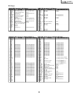
Page 50: ... t C N 8 2 C N l a n i m r e t C N 9 2 L C S Y S S A y l p p u s r e w o p h t i w n o i t a c i n u m m o c C I I M O R P E E 0 3 A D S Y S S A y l p p u s r e w o p h t i w n o i t a c i n u m m o c C I I M O R P E E 1 3 1 D X T e t o n m a r g o r p a e d i s t u o e h t h t i w n o i t a c i n u m m o C 2 3 1 D X R e t o n m a r g o r p a e d i s t u o e h t h t i w n o i t a c i n u m m o C 3...

Page 51: ... p m o c o r c i m l e n a P 6 7 C N l a n i m r e t C N 7 7 L C S _ C D D r e v i e c e r a i d e m a h t i w n o i t a c i n u m m o c C I I 8 7 A D S _ C D D r e v i e c e r a i d e m a h t i w n o i t a c i n u m m o c C I I 9 7 C N l a n i m r e t C N 0 8 C N l a n i m r e t C N 1 8 T E D _ W E D t u p n i r o s n e s n o i t a s n e d n o c w e d e h T 2 8 C N l a n i m r e t C N 3 8 C N l a...

Page 52: ...s e r d d A 5 2 7 1 O R A l a n g i s R t u p t u o a t a d s s e r d d A 6 2 S S V D N G 7 2 7 1 O B A l a n g i s B t u p t u o a t a d s s e r d d A 8 2 7 1 O G A l a n g i s G t u p t u o a t a d s s e r d d A 9 2 8 1 O G A l a n g i s G t u p t u o a t a d s s e r d d A 0 3 9 1 O B A l a n g i s B t u p t u o a t a d s s e r d d A 1 3 5 1 T A D U s u b a t a d r e t u p m o c o r c i M 2 3 2 ...

Page 53: ...t t u p n i l a n g i s t c e p s a B e r u t c i p R e h T 8 7 6 I B R t i b h t x i s e h t t u p n i l a n g i s t c e p s a B e r u t c i p R e h T 9 7 4 I B R t i b h t r u o f e h t t u p n i l a n g i s t c e p s a B e r u t c i p R e h T 0 8 9 0 S S V O D N G 1 8 B T S R t u p n i t e s e R 2 8 8 I B G t i b h t h g i e e h t t u p n i l a n g i s t c e p s a B e r u t c i p G e h T 3 8 8 ...

Page 54: ...1 6 1 O B A l a n g i s B t u p t u o a t a d s s e r d d A 5 2 1 6 1 O G A l a n g i s G t u p t u o a t a d s s e r d d A 6 2 1 8 1 O R A l a n g i s R t u p t u o a t a d s s e r d d A 7 2 1 9 1 O G A l a n g i s G t u p t u o a t a d s s e r d d A 8 2 1 5 0 E D D V O y l p p u s r e w o p V 3 3 9 2 1 3 1 T A D U s u b a t a d r e t u p m o c o r c i M 0 3 1 0 1 T A D U s u b a t a d r e t u p ...

Page 55: ... 7 1 0 1 S S V O D N G 7 7 1 4 I B G t i b h t r u o f e h t t u p n i l a n g i s t c e p s a B e r u t c i p G e h T 8 7 1 1 I B G t i b t s r i f e h t t u p n i l a n g i s t c e p s a B e r u t c i p G e h T 9 7 1 9 I B B t i b h t n i n e h t t u p n i l a n g i s t c e p s a B e r u t c i p B e h T 0 8 1 5 I B B t i b h t f i f e h t t u p n i l a n g i s t c e p s a B e r u t c i p B e h T...

Page 56: ...e t u p m o c o r c i M 5 2 2 4 1 I R D A U s u b s s e r d d a r e t u p m o c o r c i M 6 2 2 9 0 E D D V O y l p p u s r e w o p V 3 3 7 2 2 1 1 I R D A U s u b s s e r d d a r e t u p m o c o r c i M 8 2 2 8 I R D A U s u b s s e r d d a r e t u p m o c o r c i M 9 2 2 4 I R D A U s u b s s e r d d a r e t u p m o c o r c i M 0 3 2 3 T I B t i b d r i h t e h t t u p t u o o N d l e i f b u S ...

Page 57: ... A e r u t c i p R e h T 1 7 2 N U R E E R F t u p n i l o r t n o c n u r e e r f e h T 2 7 2 8 I A G t i b h t h g i e e h t t u p n i l a n g i s t c e p s a A e r u t c i p G e h T 3 7 2 5 I A G t i b h t f i f e h t t u p n i l a n g i s t c e p s a A e r u t c i p G e h T 4 7 2 1 I A G t i b t s r i f e h t t u p n i l a n g i s t c e p s a A e r u t c i p G e h T 5 7 2 8 I A B t i b h t h g...

Page 58: ... s e r d d A 6 2 3 C N l a n i m r e t C N 7 2 3 5 2 O G A l a n g i s G t u p t u o a t a d s s e r d d A 8 2 3 S S V D N G 9 2 3 3 2 O B A l a n g i s B t u p t u o a t a d s s e r d d A 0 3 3 E D D V y l p p u s r e w o p V 3 3 1 3 3 1 2 O B A l a n g i s B t u p t u o a t a d s s e r d d A 2 3 3 S S V D N G 3 3 3 D P V D N G 4 3 3 E D D V y l p p u s r e w o p V 3 3 5 3 3 0 I B R t i b 0 e h t...

Page 59: ... TC SOT 25 TOP VIEW Pin No Pin name Functions 1 TC SUB TPLH control pin Substate pin 2 3 GND GND pin 4 VOUT Reset signal output pin 5 VCC VCC pin voltage detect pin Pin Assignment Top View PST9246N DIGITAL VIDEO ASSY IC1208 Reset IC Block Diagram Pin Function ...

Page 60: ...cted to external clock other than crystal leave Xout pin2 unconnected 7 3 S0 S1 I CMOS TTL Digital control inputs to select input frequency range and output frequency scaling Refer to Tables 7 and 8 for selection S0 has internal pulldown S1 has internal pullup 4 LF I Analog Loop Filter Single ended tri state output of the phase detector A two pole passive loop filter is connected to Loop Filter LF...

Page 61: ...COM VCC VS VB HO 13 N C 17 N C 14 IN2 15 SD1 16 IN1 18 IN4 19 SD2 20 IN3 21 PL2 30 PL1 PL1 25 PC2 24 PC2 26 PC1 PC1 22 PL2 23 N C 31 N C 36 N C 34 POWER GND 35 POWER GND 33 POWER GND 32 POWER GND 28 N C 12 SUB GND 9 SIG GND 6 VCC 7 VDD 10 SIG GND TR1 TR8 R4 R9 R10 R3 TR3 TR4 VDD IC2 C5 C4 C6 TR9 TR5 TR5 D4 D3 R15 R5 D7 D5 D6 D8 D9 D10 HIN SD LIN VSS LO COM VCC VS VB HO TR10 R12 R11 R6 ZD1 R13 C7 C...

Page 62: ...river IC Driver IC Driver IC Driver IC IC6501 Buffer IC Driver IC Driver IC Driver IC Driver IC ADR CONNECT A ASSY AA1 CLK LE VADR2 VADR2 BRIDGE D ASSY BGD1 CLAMP CLAMP A ASSY CLA1 VADR2 CLAMP Q6706 Q6711 VADR Gen K2 K3 K1 SAB3 SAB1 SAB2 VADR2 VADR2 ADR_CO 60 IC5 VCC_VH PSUS VCP VC_VF VC_VF V_OFS VCC_VH V_IC5V V 3V_I V 3V V 3V_IC V 2V_IC V 2V_I V 5V_STB TXD RX I2 LED_SIG RE TXD0 RX0 V 3V V 3V BA2 ...

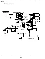
Page 63: ...0 BUFF CCKM IC4007 COMPR SW_TRG F_KEY1 F_KEY2 Q4011 DRIVER LED_G LED_R I2C Q4401 BUFF L_CH Q4402 BUFF LED_G LED_R REM KEY1 KEY2 SPR SPL R_CH CN4401 CN4007 CN4009 C4043 HPF IC4010 NON_SYSTEM_DET R4093 R4098 BIAS IC4013 STB_DET S4001 S4004 etc MODEL_INFO IC4011 I O_EXPANDER Q4005 Q4006 5V 3 3V I2C_LEVEL_SHIFT IC4204 IC4203 CONF_ROM IC4201 DDC_ROM Q4201 Q4202 5V 3 3V I2C_LEVEL_SHIFT TMDS_RXCORE CONTE...

Page 64: ...ave 0 3 3V swing square wave 0 3 3V swing square wave 0 3 3V swing square wave 0 3 3V swing square wave 0 3 3V swing square wave 0 3 3V swing square wave 0 3 3V swing square wave 0 3 3V swing square wave 0 3 3V swing square wave 0 3 3V swing square wave 0 3 3V swing square wave 0 3 3V swing square wave 0 3 3V swing square wave 0 3 3V swing square wave 0 3 3V swing square wave 0 3 3V swing square w...

Page 65: ...ft section ADR CONNECT A D Assy Right section Y DRIVE Assy X DRIVE Assy ADR RESONANCE Assy 5V 5V PC_VIDEO ADR_K_EMG STOPB 3 3V 3 3V 12V ADR K PD U ADR PD APD MUTE EXD TXD RST2 RST PU EXD RXD RESET RESET RXD BUSY REQ_PU ADR K PD D DEW DET RELAY TEMP1 STB5V STB5V STB5V 3 3V 2 5V 3 3V 3 3V 3 3V VD HD VD 31 APLR STB5V 2 5V IIC BUS RGB 2 phase 8 bit VD HD DE CLK Address BUS Data BUS Control Signal TXDO...

Page 66: ...0 STK795 460 Pulse Module IC3201 STK795 460 Pulse Module T3701 VRN D D CONV XCP MSK XSUS MSK VCP PLD SUSOUT A 37 40 29 30 K3105 PSUS K3107 IC3103 IC3104 TND301S Q3103 Q3104 Q3109 Q3105 Q3124 Q3106 Q3125 SUSOUT B 37 40 29 30 K3106 IC3106 IC3107 TND301S Q3110 Q3114 Q3111 Q3112 Q3126 Q3113 Q3127 To X CONNECTOR ASSY IC3110 TND301S IC3113 TND301S charge pump circuit From DIGITAL VIDEO ASSY Photo couple...

Page 67: ...013 IC2005 TC74ACT541FT Dew DET circuit Photo Coupler 2 9 11 18 OC2 2 Y3 Y5 Photo Coupler SUS muteDET circuit Q2215 Q2217 Q2226 IC2217 TND301S Q2227 Q2220 Q2221 Q2232 Q2233 IC2216 TND301S charge pump circuit YPR U1 YPR U2 VSUS SUSGND Photo Coupler VOFS D D CONV D GND 13 5V SUSGND D GND IC5V VF D D CONV IC5V UVP VOFS UVP VOFS OVP VH UVP VH OVP VOFS VF IC5V VF VH YSOFT D YOFS YCP MSK VH VH IC5V 13 5...

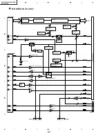
Page 68: ...IC8801 D8804 DC AC AC 5V SW ADR D DC CLK ADR U ADR B 12V IC8802 IC8802 IC8803 DGND VADR ADRGND CLR ADROUT CN8803 IC8804 Current Voltage Convert Block Over Current DET Block ADR Output Resistance Load Block P D Output Block BUFF Block Inversion Block Additional Block Conparator EMG ON Flip Flop 5V REG H EMG1 OFF L EMG1 ON H V MID CLAMP OFF L V MID CLAMP ON Conparator EMG OFF Ë SUB ADDRESS A and B A...

Page 69: ...C6721 Q6708 ADR U Q6709 ADR D SW CN6701 ADR OUT L6704 IC6702 Q6702 Q6705 VADR V MID ADR D ADRGND C6722 Q6710 DGND Q6711 SW CN6703 DGND IC6703 Q6703 Q6712 V MID C6716 C6718 ADRGND ICP S1 0 ADR B Pre Drive ADR U Pre Drive ADR U Drive ADR D Pre Drive ADR D Drive ADR B Drive CAUTION FOR CONTINUED PROTECTION AGAINST RISK OF FIRE REPLACE ONLY WITH SAME TYPE NO ICP S1 0 MFD BY ROHM CO LTD FOR IC6704 Ë AD...

Page 70: ...1 CN6501 Buffer BRIDGE ASSY OPEN PD HZ LBLK HBLK LE CLK Address Module TCP Address Module TCP Address Module TCP Address Module TCP DATA_R DATA_G DATA_B DATA_R DATA_G DATA_B DATA_R DATA_G DATA_B DATA_R DATA_G DATA_B DATA_R DATA_G DATA_B DATA_R DATA_G DATA_B DATA_R DATA_G DATA_B DATA_R DATA_G DATA_B HZ LBLK HBLK LE CLK ...

Page 71: ...RMINAL IC5201 NJM2193L IC5202 CXA2021S IC5002 LA4628 No Voltage V No Voltage V 1 5 9 12 5 25 2 0 13 1 73 3 5 95 14 5 95 4 5 94 15 5 92 5 5 98 16 5 91 6 6 02 17 5 93 7 6 02 18 5 92 8 7 38 19 5 94 9 5 95 20 5 95 10 1 55 21 11 91 11 5 24 22 5 9 No Voltage V No Voltage V 1 5 95 16 11 91 2 5 94 17 0 3 5 84 18 0 4 5 98 19 5 98 5 5 98 20 5 91 6 5 97 21 5 97 7 5 98 22 5 98 8 5 98 23 5 98 9 5 98 24 5 98 10...

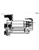
Page 72: ... 2 3 4 1 2 3 4 PZ 43HV2 PZ 43HV2E PZ 43HV2U PZ 43HV2E 9GJAEK1071 10A PZ 43HV2U 9GJAEK1069 10A NOTE FOR FUSE REPLACEMENT FOR CONTINUED PROTECTION AGAINST RISK OF FIRE REPLACE WITH SAME TYPE AND RATINGS ONLY CAUTION OVERALL WIRING DIAGRAM ...

Page 73: ...pin 8 YSUS_B V 2V div H 2msec div 7 K1308 VDRB R1343 pin 8 RDAT_DL0 V 2V div H 4msec div 8 K1308 VDRB IC1501 pin 15 LBLK V 2V div H 2msec div 9 K1308 VDRB IC1501 pin 13 LE V 2V div H 2msec div 10 IC1501 pin 13 LE IC1501 pin 11 ADRCLK V 2V div H 200nsec div 10 IC1501 pin 13 LE IC1501 pin 11 ADRCLK V 2V div H 20nsec div 1 K1327 VDI K1328 HDI V 2V div H 10µsec div 2 K1327 VDI CN1004 pin 49 R DIGITAL ...

Page 74: ... 2msec div Input VIDEO Signal Color bar 1 CH1 IC8801 pin 3 CH2 IC8801 pin 7 CH3 IC8802 pin 1 V 2V div H 2msec div Input VIDEO Signal Color bar CH1 H 2msec div CH2 CH3 V MID CLAMP ASSY 2 CH1 Q9006 Base CLAMP REF V CH2 D9010 Anode MID CH3 Q9006 Collector V 10V div H 2msec div Input PC Signal Color bar 1 CH1 Q9006 Base CLAMP REF V CH2 D9010 Anode MID CH3 Q9006 Collector V 10V div H 2msec div Input VI...

Page 75: ...ec div 8 CN5301 pin 1 L GND V 1V div H 0 2msec div 7 1 10 9 CN5301 pin 2 L GND V 1V div H 0 2msec div 10 CN5301 pin 1 L pin 2 L V 2V div H 0 2msec div AUDIO SECTION Video Input Signal FULL FIELD COLOR BAR Audio Input Signal 1kHz Sine Carve 0 2Vrms Volume 60 MAX AV Selection STANDARD SRS OFF FOCUS OFF Measurement condition GND and the speaker output side becomes a short state on the oscilloscope Wr...

Page 76: ...v H 5µsec div Sustain Waveform sustain ch 1 K3107 X PSUS K3201 SUSGND V 50V div H 2µsec div ch 2 K2220 Y PSUS K2219 SUSGND V 50V div H 2µsec div Sustain Waveform reset pulse ch 1 K3107 X PSUS K3201 SUSGND V 100V div H 5µsec div ch 2 K2220 Y PSUS K2219 SUSGND V 100V div H 5µsec div Y Drive Pulse Control Waveform 1 field ch 1 K2220 Y PSUS K2219 SUSGND V 100V div H 2msec div ch 2 K2039 YCP_MSK K2024 ...

Page 77: ...81 80 A B C D 5 6 7 5 6 7 8 A B C D 2 3 4 1 2 3 4 PZ 43HV2 PZ 43HV2E PZ 43HV2U Ë SCAN A ASSY ...

Page 78: ...83 82 A B C D 5 6 7 5 6 7 8 A B C D 2 3 4 1 2 3 4 PZ 43HV2 PZ 43HV2E PZ 43HV2U Ë SCAN B ASSY ...

Page 79: ...84 A B C D 2 3 4 1 2 3 4 PZ 43HV2 PZ 43HV2E PZ 43HV2U Ë X CONNECTOR A and B ASSYS ...

Page 80: ...85 A B C D 1 2 3 1 2 3 4 PZ 43HV2 PZ 43HV2E PZ 43HV2U Ë BRIDGE A D ASSYS ...

Page 81: ...86 A B C D 2 3 4 1 2 3 4 PZ 43HV2 PZ 43HV2E PZ 43HV2U Ë CLAMP A and B ASSYS ...

Page 82: ...87 PZ 43HV2 PZ 43HV2E PZ 43HV2U ...

Page 83: ...89 88 A B C D 5 6 7 5 6 7 8 A B C D 2 3 4 1 2 3 4 PZ 43HV2 PZ 43HV2E PZ 43HV2U Ë ADR CONNECT A ASSY 47 6 3 47 6 3 47 6 3 AWV1928 ...

Page 84: ...91 90 A B C D 5 6 7 5 6 7 8 A B C D 2 3 4 1 2 3 4 PZ 43HV2 PZ 43HV2E PZ 43HV2U Ë ADR CONNECT B ASSY 47 6 3 47 6 3 47 6 3 AWV1928 ...

Page 85: ...93 92 A B C D 5 6 7 5 6 7 8 A B C D 2 3 4 1 2 3 4 PZ 43HV2 PZ 43HV2E PZ 43HV2U Ë ADR CONNECT C ASSY 47 6 3 47 6 3 47 6 3 AWV1928 ...

Page 86: ...95 94 A B C D 5 6 7 5 6 7 8 A B C D 2 3 4 1 2 3 4 PZ 43HV2 PZ 43HV2E PZ 43HV2U Ë ADR CONNECT D ASSY 47 6 3 47 6 3 47 6 3 AWV1928 ...

Page 87: ... B C D 2 3 4 1 2 3 4 PZ 43HV2 PZ 43HV2E PZ 43HV2U Ë ADR RESONANCE ASSY CAUTION FOR CONTINUED PROTECTION AGAINST RISK OF FIRE REPLACE ONLY WITH SAME TYPE NO ICP S1 0 MFD BY ROHM CO LTD FOR IC6704 AWZ6692 or 6693 AWZ6674 6677 AXY1056 ...

Page 88: ...99 98 A B C D 5 6 7 5 6 7 8 A B C D 2 3 4 1 2 3 4 PZ 43HV2 PZ 43HV2E PZ 43HV2U Ë X DRIVE ASSY 1 2 X LOGIC BLOCK ...

Page 89: ...101 100 A B C D 5 6 7 5 6 7 8 A B C D 2 3 4 1 2 3 4 PZ 43HV2 PZ 43HV2E PZ 43HV2U Ë X DRIVE ASSY 2 2 X SUS BLOCK ...

Page 90: ...103 102 A B C D 5 6 7 5 6 7 8 A B C D 2 3 4 1 2 3 4 PZ 43HV2 PZ 43HV2E PZ 43HV2U Ë Y DRIVE ASSY 1 3 Y LOGIC DRIVE BLOCK ...

Page 91: ...105 104 A B C D 5 6 7 5 6 7 8 A B C D 2 3 4 1 2 3 4 PZ 43HV2 PZ 43HV2E PZ 43HV2U Ë Y DRIVE ASSY 2 3 Y DRIVE SUS BLOCK ...

Page 92: ...107 106 A B C D 5 6 7 5 6 7 8 A B C D 2 3 4 1 2 3 4 PZ 43HV2 PZ 43HV2E PZ 43HV2U Ë Y DRIVE ASSY 3 3 Y DRIVE SCAN BLOCK ...

Page 93: ...109 108 A B C D 5 6 7 5 6 7 8 A B C D 2 3 4 1 2 3 4 PZ 43HV2 PZ 43HV2E PZ 43HV2U Ë SUB ADDRESS A ASSY ...

Page 94: ...111 110 A B C D 5 6 7 5 6 7 8 A B C D 2 3 4 1 2 3 4 PZ 43HV2 PZ 43HV2E PZ 43HV2U Ë SUB ADDRESS B ASSY ...

Page 95: ...113 112 A B C D 5 6 7 5 6 7 8 A B C D 2 3 4 1 2 3 4 PZ 43HV2 PZ 43HV2E PZ 43HV2U Ë DIGITAL VIDEO ASSY 1 10 DIGITAL BLOCK ...

Page 96: ...115 114 A B C D 5 6 7 5 6 7 8 A B C D 2 3 4 1 2 3 4 PZ 43HV2 PZ 43HV2E PZ 43HV2U 1 2 2 2 1 2 Large size SCH diagram Ë DIGITAL VIDEO ASSY 2 10 PANEL UCOM BLOCK ...

Page 97: ...117 116 A B C D 5 6 7 5 6 7 8 A B C D 2 3 4 1 2 3 4 PZ 43HV2 PZ 43HV2E PZ 43HV2U 1 2 2 2 2 2 Large size SCH diagram ...

Page 98: ...119 118 A B C D 5 6 7 5 6 7 8 A B C D 2 3 4 1 2 3 4 PZ 43HV2 PZ 43HV2E PZ 43HV2U Ë DIGITAL VIDEO ASSY 3 10 MODULE UCOM BLOCK 1 2 2 2 1 2 Large size SCH diagram ...

Page 99: ...121 120 A B C D 5 6 7 5 6 7 8 A B C D 2 3 4 1 2 3 4 PZ 43HV2 PZ 43HV2E PZ 43HV2U 1 2 2 2 2 2 Large size SCH diagram ...

Page 100: ...123 122 A B C D 5 6 7 5 6 7 8 A B C D 2 3 4 1 2 3 4 PZ 43HV2 PZ 43HV2E PZ 43HV2U 1 2 2 2 1 2 Large size SCH diagram Ë DIGITAL VIDEO ASSY 4 10 IC31 L BLOCK ...

Page 101: ...125 124 A B C D 5 6 7 5 6 7 8 A B C D 2 3 4 1 2 3 4 PZ 43HV2 PZ 43HV2E PZ 43HV2U 1 2 2 2 2 2 Large size SCH diagram ...

Page 102: ...127 126 A B C D 5 6 7 5 6 7 8 A B C D 2 3 4 1 2 3 4 PZ 43HV2 PZ 43HV2E PZ 43HV2U 1 2 2 2 1 2 Large size SCH diagram Ë DIGITAL VIDEO ASSY 5 10 IC31 R BLOCK ...

Page 103: ...129 128 A B C D 5 6 7 5 6 7 8 A B C D 2 3 4 1 2 3 4 PZ 43HV2 PZ 43HV2E PZ 43HV2U 1 2 2 2 2 2 Large size SCH diagram ...

Page 104: ...131 130 A B C D 5 6 7 5 6 7 8 A B C D 2 3 4 1 2 3 4 PZ 43HV2 PZ 43HV2E PZ 43HV2U 1 2 2 2 1 2 Large size SCH diagram Ë DIGITAL VIDEO ASSY 6 10 ADDRESS CONNECTOR U BLOCK ...

Page 105: ...133 132 A B C D 5 6 7 5 6 7 8 A B C D 2 3 4 1 2 3 4 PZ 43HV2 PZ 43HV2E PZ 43HV2U 1 2 2 2 2 2 Large size SCH diagram ...

Page 106: ...135 134 A B C D 5 6 7 5 6 7 8 A B C D 2 3 4 1 2 3 4 PZ 43HV2 PZ 43HV2E PZ 43HV2U 1 2 2 2 1 2 Large size SCH diagram Ë DIGITAL VIDEO ASSY 7 10 ADDRESS CONNECTOR D BLOCK ...

Page 107: ...137 136 A B C D 5 6 7 5 6 7 8 A B C D 2 3 4 1 2 3 4 PZ 43HV2 PZ 43HV2E PZ 43HV2U 1 2 2 2 2 2 Large size SCH diagram ...

Page 108: ...139 138 A B C D 5 6 7 5 6 7 8 A B C D 2 3 4 1 2 3 4 PZ 43HV2 PZ 43HV2E PZ 43HV2U 1 2 2 2 1 2 Large size SCH diagram Ë DIGITAL VIDEO ASSY 8 10 IC23 BLOCK ...

Page 109: ...141 140 A B C D 5 6 7 5 6 7 8 A B C D 2 3 4 1 2 3 4 PZ 43HV2 PZ 43HV2E PZ 43HV2U 1 2 2 2 2 2 Large size SCH diagram ...

Page 110: ...143 142 A B C D 5 6 7 5 6 7 8 A B C D 2 3 4 1 2 3 4 PZ 43HV2 PZ 43HV2E PZ 43HV2U Ë DIGITAL VIDEO ASSY 9 10 CLK GENERATOR BLOCK ...

Page 111: ...145 144 A B C D 5 6 7 5 6 7 8 A B C D 2 3 4 1 2 3 4 PZ 43HV2 PZ 43HV2E PZ 43HV2U Ë DIGITAL VIDEO ASSY 10 10 D D CONV BLOCK ...

Page 112: ... 146 A B C D 5 6 7 5 6 7 8 A B C D 2 3 4 1 2 3 4 PZ 43HV2 PZ 43HV2E PZ 43HV2U 3 3V 3 3V 0V 5V 5V 5V 2 5V 3 1V 3 1V 0V 0V 5V 5V 5V 1 2 2 2 1 2 Large size SCH diagram Ë MR INTERFACE ASSY 1 3 INTERFACE BLOCK ...

Page 113: ...149 148 A B C D 5 6 7 5 6 7 8 A B C D 2 3 4 1 2 3 4 PZ 43HV2 PZ 43HV2E PZ 43HV2U 3 3V 0 5V I2C 0 3 3V I2C 0V 5V 0V 5V 5V 1 2 2 2 2 2 Large size SCH diagram ...

Page 114: ...151 150 A B C D 5 6 7 5 6 7 8 A B C D 2 3 4 1 2 3 4 PZ 43HV2 PZ 43HV2E PZ 43HV2U DVI RECEIVER with SCALER EDID ROM SiI861 Initialize Data ROM Ë MR INTERFACE ASSY 2 3 TMDS RECEIVER BLOCK ...

Page 115: ...153 152 A B C D 5 6 7 5 6 7 8 A B C D 2 3 4 1 2 3 4 PZ 43HV2 PZ 43HV2E PZ 43HV2U Ë MR INTERFACE ASSY 3 3 AUDIO BLOCK ...

Page 116: ...155 154 A B C D 5 6 7 5 6 7 8 A B C D 2 3 4 1 2 3 4 PZ 43HV2 PZ 43HV2E PZ 43HV2U Ë LED FRONT KEY FRONT KEY CONN IR RECEIVE P and SENSOR ASSYS 5V 5V Panel Temp TEMP1 Voltage 0V ...

Page 117: ...1 6 6 02 17 5 93 7 6 02 18 5 92 8 7 38 19 5 94 9 5 95 20 5 95 10 1 55 21 11 91 11 5 24 22 5 9 No Voltage V No Voltage V 1 5 95 16 11 91 2 5 94 17 0 3 5 84 18 0 4 5 98 19 5 98 5 5 98 20 5 91 6 5 97 21 5 97 7 5 98 22 5 98 8 5 98 23 5 98 9 5 98 24 5 98 10 5 97 25 5 97 11 5 97 26 5 98 12 5 98 27 5 98 13 5 96 28 5 84 14 5 98 29 5 94 15 0 30 5 95 No Voltage V 1 1 6 2 7 5 3 0 4 3 37 5 2 29 6 1 6 7 1 97 8...

Page 118: ...158 A B C D 2 3 4 1 2 3 4 PZ 43HV2 PZ 43HV2E PZ 43HV2U Ë SP TERMINAL ASSY ...

Page 119: ...159 PZ 43HV2 PZ 43HV2E PZ 43HV2U ...

Page 120: ...161 160 A B C D 5 6 7 5 6 7 8 A B C D 2 3 4 1 2 3 4 PZ 43HV2 PZ 43HV2E PZ 43HV2U Ë SW POWER SUPPLY MODULE 1 3 Refer to SW POWER SUPPLY MODULE 2 3 ...

Page 121: ...163 162 A B C D 5 6 7 5 6 7 8 A B C D 2 3 4 1 2 3 4 PZ 43HV2 PZ 43HV2E PZ 43HV2U Ë SW POWER SUPPLY MODULE 2 3 ...

Page 122: ...164 A B C D 2 3 4 1 2 3 4 PZ 43HV2 PZ 43HV2E PZ 43HV2U Ë SW POWER SUPPLY MODULE 3 3 ...

Page 123: ...grams is shown below 3 The parts mounted on this PWB include all necessary parts for several destinations For further information for respective destinations be sure to check with the schematic diagram 4 View point of PWB diagrams Symbol In PWB Diagrams Symbol In Schematic Diagrams Part Name B C E D D G G S S B C E B C E D G S B C E B C E B C E Transistor Transistor with resistor Field effect tran...

Page 124: ... B C D 2 3 4 1 2 3 4 PZ 43HV2 PZ 43HV2E PZ 43HV2U Ë X CONNECTOR A and B ASSYS X CONNECTOR A ASSY X CONNECTOR A ASSY X CONNECTOR B ASSY X CONNECTOR B ASSY ANP2005 B ANP2005 B ANP2005 B ANP2005 B SIDE A SIDE B ...

Page 125: ...167 A B C D 1 2 3 1 2 3 4 PZ 43HV2 PZ 43HV2E PZ 43HV2U Ë SCAN A ASSY ANP2005 B ANP2005 B SCAN A ASSY SCAN A ASSY SIDE A SIDE B ...

Page 126: ...168 A B C D 2 3 4 1 2 3 4 PZ 43HV2 PZ 43HV2E PZ 43HV2U ANP2005 B ANP2005 B SCAN B ASSY SCAN B ASSY SIDE A SIDE B Ë SCAN B ASSY ...

Page 127: ...169 A B C D 1 2 3 1 2 3 4 PZ 43HV2 PZ 43HV2E PZ 43HV2U Ë BRIDGE A D ASSYS SIDE A ANP2005 B ANP2005 B ANP2005 B ANP2005 B BRIDGE A ASSY BRIDGE B ASSY BRIDGE C ASSY BRIDGE D ASSY ...

Page 128: ...170 A B C D 2 3 4 1 2 3 4 PZ 43HV2 PZ 43HV2E PZ 43HV2U ANP2006 A ANP2006 A ANP2006 A ANP2006 A ADR CONNECT D ASSY ADR CONNECT C ASSY ADR CONNECT B ASSY ADR CONNECT A ASSY SIDE A Ë ADR CONNECT A D ASSYS ...

Page 129: ...171 A B C D 1 2 3 1 2 3 4 PZ 43HV2 PZ 43HV2E PZ 43HV2U Ë SUB ADDRESS A and B ASSYS ANP1984 C SUB ADDRESS B ASSY ANP1984 C SUB ADDRESS A ASSY SIDE A SIDE A ...

Page 130: ...173 172 A B C D 5 6 7 5 6 7 8 A B C D 2 3 4 1 2 3 4 PZ 43HV2 PZ 43HV2E PZ 43HV2U ANP1983 D X DRIVE ASSY SIDE A Ë X DRIVE ASSY ...

Page 131: ...175 174 A B C D 5 6 7 5 6 7 8 A B C D 2 3 4 1 2 3 4 PZ 43HV2 PZ 43HV2E PZ 43HV2U ANP1983 D X DRIVE ASSY SIDE B ...

Page 132: ...177 176 A B C D 5 6 7 5 6 7 8 A B C D 2 3 4 1 2 3 4 PZ 43HV2 PZ 43HV2E PZ 43HV2U ANP1984 C Y DRIVE ASSY SIDE A Ë Y DRIVE ASSY ...

Page 133: ...179 178 A B C D 5 6 7 5 6 7 8 A B C D 2 3 4 1 2 3 4 PZ 43HV2 PZ 43HV2E PZ 43HV2U ANP1985 C DIGITAL VIDEO ASSY SIDE A Ë DIGITAL VIDEO ASSY ...

Page 134: ...181 180 A B C D 5 6 7 5 6 7 8 A B C D 2 3 4 1 2 3 4 PZ 43HV2 PZ 43HV2E PZ 43HV2U ANP1985 C DIGITAL VIDEO ASSY SIDE B ...

Page 135: ... CONN ASSY IR RECEIVE P ASSY SENSOR ASSY ANP1997 B ANP1997 B ANP1997 B ANP1997 B ANP1997 B LED ASSY FRONT KEY ASSY FRONT KEY CONN ASSY IR RECEIVE P ASSY SENSOR ASSY ANP1997 B ANP1997 B ANP1997 B ANP1997 B ANP1997 B SIDE A SIDE B Ë LED FRONT KEY FRONT KEY CONN IR RECEIVE P and SENSOR ASSYS ...

Page 136: ...183 A B C D 1 2 3 1 2 3 4 PZ 43HV2 PZ 43HV2E PZ 43HV2U Ë AUDIO AMP and SP TERMINAL ASSYS AUDIO AMP ASSY SP TERMINAL ASSY ANP2001 B ANP2001 B SIDE A SIDE A ...

Page 137: ...184 A B C D 2 3 4 1 2 3 4 PZ 43HV2 PZ 43HV2E PZ 43HV2U MR INTERFACE ASSY ANP1997 B SIDE A Ë MR INTERFACE ASSY ...

Page 138: ...185 A B C D 1 2 3 1 2 3 4 PZ 43HV2 PZ 43HV2E PZ 43HV2U MR INTERFACE ASSY ANP1997 B SIDE B ...

Page 139: ...ng such features are identified by å in the Replacement Parts Lists The use of a substitute replacement part which does not have the same safety characteristics as the factory recommended replace ment parts shown in this service manual may create shock fire or other hazards HOW TO ORDER REPLACEMENT PARTS To have your order filled promptly and correctly please furnish the following informations 1 M...

Page 140: ...201 9GJSN755860PJ J Scan IC BH IC6202 9GJSN755860PJ J Scan IC BH IC6203 9GJSN755860PJ J Scan IC BH IC6204 9GJSN755860PJ J Scan IC BH IC6205 9GJSN755860PJ J Scan IC BH IC6206 9GJSN755860PJ J Scan IC BH CAPACITORS C6201 9GJACG1088 J 0 1 250V Ceramic AL C6202 9GJACG1088 J 0 1 250V Ceramic AL C6212 9GJACG1088 J 0 1 250V Ceramic AL C6213 9GJACG1088 J 0 1 250V Ceramic AL C6222 9GJACG1088 J 0 1 250V Cera...

Page 141: ...SRYF104Z1 J 0 1 50V Ceramic AD C6247 9GJCKSRYF104Z1 J 0 1 50V Ceramic AD C6261 9GJCKSRYF104Z1 J 0 1 50V Ceramic AD RESISTORS R6207 9GJRAB4C221J J Resistor Array AL R6209 9GJRAB4C221J J Resistor Array AL R6222 9GJRAB4C221J J Resistor Array AL R6228 9GJRAB4C221J J Resistor Array AL R6232 9GJRAB4C221J J Resistor Array AL R6239 9GJRAB4C221J J Resistor Array AL R6201 9GJRS1 16S221J J 220 1 16W Chip AC ...

Page 142: ... 0 1 16V Ceramic AD C6524 9GJCKSRYF104Z1 J 0 1 16V Ceramic AD C6525 9GJCKSRYF104Z1 J 0 1 16V Ceramic AD C6532 9GJCKSRYF104Z1 J 0 1 16V Ceramic AD C6535 9GJCKSRYF104Z1 J 0 1 16V Ceramic AD RESISTORS R6519 9GJRAB4C100J J Resistor Array AL R6520 9GJRAB4C100J J Resistor Array AL R6521 9GJRAB4C100J J Resistor Array AL R6522 9GJRAB4C100J J Resistor Array AL R6526 9GJRAB4C100J J Resistor Array AL R6528 9...

Page 143: ...0J J 0 1 16W Chip AC R6651 9GJRS1 16S0R0J J 0 1 16W Chip AC R6652 9GJRS1 16S0R0J J 0 1 16W Chip AC R6653 9GJRS1 16S0R0J J 0 1 16W Chip AC R6625 9GJRS1 16S100J J 10 1 16W Chip AC R6627 9GJRS1 16S100J J 10 1 16W Chip AC R6629 9GJRS1 16S100J J 10 1 16W Chip AC R6632 9GJRS1 16S100J J 10 1 16W Chip AC R6640 9GJRS1 16S100J J 10 1 16W Chip AC R6642 9GJRS1 16S100J J 10 1 16W Chip AC R6644 9GJRS1 16S100J J...

Page 144: ...C6928 9GJACG1094 J 330p 100V Ceramic AL C6931 9GJACH1341 J 47 6 3V Electrolytic AL C6933 9GJACH1341 J 47 6 3V Electrolytic AL C6934 9GJACH1341 J 47 6 3V Electrolytic AL C6936 9GJCCSRCH121J5 J 120p 50V Ceramic AD C6937 9GJCCSRCH121J5 J 120p 50V Ceramic AD C6938 9GJCCSRCH121J5 J 120p 50V Ceramic AD C6907 9GJCKSRYF104Z1 J 0 1 16V Ceramic AD C6908 9GJCKSRYF104Z1 J 0 1 16V Ceramic AD C6909 9GJCKSRYF104...

Page 145: ...6S220J J 22 1 16W Chip AC R6728 9GJRS1 16S220J J 22 1 16W Chip AC R6730 9GJRS1 16S220J J 22 1 16W Chip AC R6720 9GJRS1 16S222J J 2 2k 1 16W Chip AC R6721 9GJRS1 16S222J J 2 2k 1 16W Chip AC R6726 9GJRS1 16S222J J 2 2k 1 16W Chip AC R6727 9GJRS1 16S222J J 2 2k 1 16W Chip AC R6737 9GJRS1 16S222J J 2 2k 1 16W Chip AC R6738 9GJRS1 16S222J J 2 2k 1 16W Chip AC R6706 9GJRS1 16S4R7J J 4 7 1 16W Chip AC R...

Page 146: ...1160 J 1 5 250V MPP AN C3225 9GJACE1160 J 1 5 250V MPP AN C3226 9GJACE1160 J 1 5 250V MPP AN C3131 9GJACG1092 J 0 1 630V Ceramic AL C3139 9GJACG1092 J 0 1 630V Ceramic AL C3143 9GJACG1092 J 0 1 630V Ceramic AL C3223 9GJACG1100 J 100p 500V Ceramic AL C3224 9GJACG1100 J 100p 500V Ceramic AL C3132 9GJACH1346 J 47 350V Electrolytic AN C3200 9GJACH1348 J 330 315V Electrolytic AX C3201 9GJACH1348 J 330 ...

Page 147: ... J 100 1 16W Chip AC R3106 9GJRS1 16S102J J 1k 1 16W Chip AC R3125 9GJRS1 16S102J J 1k 1 16W Chip AC R3190 9GJRS1 16S102J J 1k 1 16W Chip AC R3110 9GJRS1 16S103J J 10k 1 16W Chip AC R3111 9GJRS1 16S103J J 10k 1 16W Chip AC R3186 9GJRS1 16S103J J 10k 1 16W Chip AC R3189 9GJRS1 16S103J J 10k 1 16W Chip AC R3191 9GJRS1 16S103J J 10k 1 16W Chip AC R3192 9GJRS1 16S103J J 10k 1 16W Chip AC R3201 9GJRS1 ...

Page 148: ...SK2201 J 2SK2201 AG Q2101 9GJHN1C01FU J HN1C01FU AL Q2102 9GJHN1C01FU J HN1C01FU AL DIODE D2101 9GJ1SS355 J Diode AD COIL L2001 9GJLFEA100J J Inductor AL CAPACITORS C2101 9GJCEHAT100M50 J 10 50V Electrolytic AC C2103 9GJCEHAT1R0M50 J 1 50V Electrolytic AL C2003 9GJCEHAT470M16 J 47 16V Electrolytic AL C2001 9GJCKSRYF104Z5 J 0 1 50V Ceramic AL C2004 9GJCKSRYF104Z5 J 0 1 50V Ceramic AL C2005 9GJCKSRY...

Page 149: ...H1348 J 330 315V Electrolytic AX C2236 9GJACH1348 J 330 315V Electrolytic AX C2253 9GJCCSRCH331J5 J 330p 50V Ceramic AD C2254 9GJCCSRCH331J5 J 330p 50V Ceramic AD C2255 9GJCCSRCH331J5 J 330p 50V Ceramic AD C2256 9GJCCSRCH331J5 J 330p 50V Ceramic AD C2257 9GJCCSRCH331J5 J 330p 50V Ceramic AD C2258 9GJCCSRCH331J5 J 330p 50V Ceramic AD C2259 9GJCCSRCH331J5 J 330p 50V Ceramic AD C2260 9GJCCSRCH331J5 J...

Page 150: ...JANK 142 J Ground Plate AC KN2205 9GJANK 142 J Ground Plate AC KN2206 9GJANK 142 J Ground Plate AC KN2207 9GJANK 142 J Ground Plate AC KN2208 9GJANK 142 J Ground Plate AC KN2209 9GJANK 142 J Ground Plate AC KN2210 9GJANK 142 J Ground Plate AC 2201 9GJAEH1049 J Spacer AL Y DRIVE SCAN BLOCK INTEGRATED CIRCUITS IC2501 9GJHCPL M611 J HCPL M611 AN IC2502 9GJHCPL M611 J HCPL M611 AN IC2505 9GJHCPL M611 ...

Page 151: ...lytic AK C2704 9GJCEHAT221M25 J 220 25V Electrolytic AE C2715 9GJCEHAT331M16 J 330 16V Electrolytic AL C2746 9GJCEHAT331M25 J 330 25V Electrolytic AL C2723 9GJCEHAT470M16 J 47 16V Electrolytic AL C2751 9GJCEHAT470M16 J 47 16V Electrolytic AL C2712 9GJCEHAT471M35 J 470 35V Electrolytic AD C2711 9GJCKSRYB103K5 J 0 01 50V Ceramic AD C2705 9GJCKSRYB104K1 J 0 1 16V Ceramic AD C2713 9GJCKSRYB104K1 J 0 1...

Page 152: ...712 AC Q8806 9GJ2SK209 J 2SK209 AL DIODES D8801 9GJ1SS355 J Diode AD D8802 9GJ1SS355 J Diode AD D8803 9GJ1SS355 J Diode AD D8809 9GJ1SS355 J Diode AD D8806 9GJDA227 J Diode AL D8807 9GJDA227 J Diode AL D8808 9GJUDZ27B J Zener Diode AD D8804 9GJUDZS5 1B J Zener Diode AD COILS L8801 9GJATH1074 J Choke Coil 100µH 0 45A AH L8802 9GJATH1081 J Coil 22µH 0 11A Chip AE L8803 9GJATH1081 J Coil 22µH 0 11A C...

Page 153: ...amic AD C8915 9GJCKSRYF104Z1 J 0 1 16V Ceramic AD C8916 9GJCKSRYF104Z1 J 0 1 16V Ceramic AD C8917 9GJCKSRYF104Z1 J 0 1 16V Ceramic AD C8920 9GJCKSRYF104Z1 J 0 1 16V Ceramic AD C8921 9GJCKSRYF104Z1 J 0 1 16V Ceramic AD RESISTORS R8906 9GJRS1 16S1002 J 10k 1 16W Chip AC R8907 9GJRS1 16S1002 J 10k 1 16W Chip AC R8937 9GJRS1 16S1002 J 10k 1 16W Chip AC R8938 9GJRS1 16S1002 J 10k 1 16W Chip AC R8941 9G...

Page 154: ...stor Array AB R1012 9GJRAB4C470J J Resistor Array AB R1013 9GJRAB4C470J J Resistor Array AB R1014 9GJRAB4C470J J Resistor Array AB R1015 9GJRAB4C470J J Resistor Array AB R1016 9GJRAB4C470J J Resistor Array AB R1017 9GJRAB4C470J J Resistor Array AB R1019 9GJRAB4C470J J Resistor Array AB R1020 9GJRAB4C470J J Resistor Array AB R1027 9GJRAB4C470J J Resistor Array AB R1032 9GJRAB4C470J J Resistor Array...

Page 155: ...0 1 16W Chip AC R1103 9GJRS1 16S471J J 470 1 16W Chip AC R1105 9GJRS1 16S472J J 4 7k 1 16W Chip AC R1106 9GJRS1 16S472J J 4 7k 1 16W Chip AC R1108 9GJRS1 16S472J J 4 7k 1 16W Chip AC R1120 9GJRS1 16S472J J 4 7k 1 16W Chip AC R1122 9GJRS1 16S472J J 4 7k 1 16W Chip AC R1123 9GJRS1 16S472J J 4 7k 1 16W Chip AC R1125 9GJRS1 16S472J J 4 7k 1 16W Chip AC R1132 9GJRS1 16S472J J 4 7k 1 16W Chip AC R1136 9...

Page 156: ...474J J 470k 1 16W Chip AC R1253 9GJRS1 16S474J J 470k 1 16W Chip AC R1257 9GJRS1 16S474J J 470k 1 16W Chip AC R1259 9GJRS1 16S474J J 470k 1 16W Chip AC R1260 9GJRS1 16S474J J 470k 1 16W Chip AC R1262 9GJRS1 16S474J J 470k 1 16W Chip AC R1255 9GJRS1 16S682J J 6 8k 1 16W Chip AC MISCELLANEOUS PARTS CN1201 9GJCKS3130 J Plug 8 pin AL CN1202 9GJCKS3130 J Plug 8 pin AL CN1203 9GJB3B PH SM3 J PH Connecto...

Page 157: ...04Z1 J 0 1 16V Ceramic AD C1709 9GJCKSRYF104Z1 J 0 1 16V Ceramic AD C1710 9GJCKSRYF104Z1 J 0 1 16V Ceramic AD C1713 9GJCKSRYF104Z1 J 0 1 16V Ceramic AD C1803 9GJCKSRYF104Z1 J 0 1 16V Ceramic AD C1804 9GJCKSRYF104Z1 J 0 1 16V Ceramic AD C1805 9GJCKSRYF104Z1 J 0 1 16V Ceramic AD RESISTORS R1502 9GJRAB4C101J J Resistor Array AB R1517 9GJRAB4C101J J Resistor Array AB R1606 9GJRAB4C101J J Resistor Arra...

Page 158: ... AC R1702 9GJRS1 16S470J J 47 1 16W Chip AC R1719 9GJRS1 16S470J J 47 1 16W Chip AC R1815 9GJRS1 16S470J J 47 1 16W Chip AC R1817 9GJRS1 16S470J J 47 1 16W Chip AC R1718 9GJRS1 16S472J J 4 7k 1 16W Chip AC R1539 9GJRS1 16S474J J 470k 1 16W Chip AC R1540 9GJRS1 16S474J J 470k 1 16W Chip AC R1541 9GJRS1 16S474J J 470k 1 16W Chip AC R1542 9GJRS1 16S474J J 470k 1 16W Chip AC R1639 9GJRS1 16S474J J 470...

Page 159: ...9GJTC74HC00AF J TC74HC00AF AL IC4012 9GJTC74HC4066A J TC74HC4066A AK IC4006 9GJTC74VHCT541 J TC74VHCT541 AM TRANSISOTRS Q4003 9GJ2SA1162 J 2SA1162 AD Q4004 9GJ2SA1162 J 2SA1162 AD Q4010 9GJ2SA1162 J 2SA1162 AD Q4007 9GJ2SC2712 J 2SC2712 AC Q4009 9GJ2SC2712 J 2SC2712 AC Q4013 9GJ2SC2712 J 2SC2712 AC Q4017 9GJ2SC2712 J 2SC2712 AC Q4018 9GJ2SC2712 J 2SC2712 AC Q4012 9GJDTC124EK J DTC124EK AD Q4016 9G...

Page 160: ...J J 0 1 16W Chip AC R4137 9GJRS1 16S0R0J J 0 1 16W Chip AC R4138 9GJRS1 16S0R0J J 0 1 16W Chip AC R4144 9GJRS1 16S0R0J J 0 1 16W Chip AC R4091 9GJRS1 16S100J J 10 1 16W Chip AC R4001 9GJRS1 16S101J J 100 1 16W Chip AC R4024 9GJRS1 16S101J J 100 1 16W Chip AC R4025 9GJRS1 16S101J J 100 1 16W Chip AC R4043 9GJRS1 16S101J J 100 1 16W Chip AC R4059 9GJRS1 16S101J J 100 1 16W Chip AC R4067 9GJRS1 16S10...

Page 161: ... 50V Ceramic Chip AD C4215 9GJCCSRCH331J5 J 330p 50V Ceramic Chip AD C4222 9GJCCSRCH331J5 J 330p 50V Ceramic Chip AD C4230 9GJCCSRCH331J5 J 330p 50V Ceramic Chip AD C4255 9GJCCSRCH331J5 J 330p 50V Ceramic Chip AD C4257 9GJCCSRCH331J5 J 330p 50V Ceramic Chip AD C4262 9GJCCSRCH471J5 J 470p 50V Ceramic Chip AD C4206 9GJCCSRCH820J5 J 82p 50V Ceramic Chip AD C4207 9GJCCSRCH820J5 J 82p 50V Ceramic Chip ...

Page 162: ...7 9GJRS1 16S222J J 2 2k 1 16W Chip AC R4201 9GJRS1 16S223J J 22k 1 16W Chip AC R4203 9GJRS1 16S223J J 22k 1 16W Chip AC R4204 9GJRS1 16S223J J 22k 1 16W Chip AC R4205 9GJRS1 16S223J J 22k 1 16W Chip AC R4206 9GJRS1 16S223J J 22k 1 16W Chip AC R4207 9GJRS1 16S223J J 22k 1 16W Chip AC R4208 9GJRS1 16S223J J 22k 1 16W Chip AC R4230 9GJRS1 16S223J J 22k 1 16W Chip AC R4259 9GJRS1 16S223J J 22k 1 16W C...

Page 163: ...AC MISCELLANEOUS PARTS CN4951 9GJKM200NA3 J Plug 3 pin AC 4901 9GJGP1UM26RK J R C Receiver unit 9GJAWZ6660 SENSOR ASSY INTEGRATED CIRCUITS IC4702 9GJLM50CIM3 J LM50CIM3 AN IC4701 9GJM5223AFP J M5223AFP AG CAPACITORS C4705 9GJCEV470M6R3 J 47 6 3V Electrolytic AD C4704 9GJCKSRYB103K5 J 0 01 50V Ceramic AD C4701 9GJCKSRYF104Z1 J 0 1 16V Ceramic AD C4702 9GJCKSRYF105Z1 J 1 10V Ceramic AD C4703 9GJCKSR...

Page 164: ...D1 4PU101J J 100 1 4W Carbon Film AL R5063 9GJRD1 4PU101J J 100 1 4W Carbon Film AL R5078 9GJRD1 4PU101J J 100 1 4W Carbon Film AL R5213 9GJRD1 4PU101J J 100 1 4W Carbon Film AL R5214 9GJRD1 4PU101J J 100 1 4W Carbon Film AL R5229 9GJRD1 4PU101J J 100 1 4W Carbon Film AL R5230 9GJRD1 4PU101J J 100 1 4W Carbon Film AL R5027 9GJRD1 4PU103J J 10k 1 4W Carbon Film AL R5051 9GJRD1 4PU103J J 10k 1 4W Ca...

Page 165: ...IDGE C Assy 3 9GJAWZ6677 J BRIDGE D Assy 4 9GJAWU1038 J Panel Chassis 43 Assy Refer to PANEL CHASSIS 43 ASSY 5 9GJAEC1872 J Circuit Board Spacer AE 6 9GJAEC1253 J PWB Spacer 7 9GJAEC1873 J Circuit Board Spacer AD 8 9GJVBB30P100FN J Screw AD 9 9GJABA1301 J Screw AG UNDER LAYER SECTION 1 PARTS LIST 4 8 1 5 3 2 2 or 3 5 7 6 Refer to PANEL CHASSIS 43 ASSY 9GJAWU1038 9 9 5 Upper side ...

Page 166: ... Code 213 PZ 43HV2 PZ 43HV2E PZ 43HV2U 3 3 1 5 3 2 Upper side 4 4 5 UNDER LAYER SECTION 2 1 9GJAWZ6668 J CLAMP A Assy 2 9GJAWZ6669 J CLAMP B Assy 3 9GJAEC1904 J Wire Saddle AL 4 9GJAEC1736 J Locking Card Spacer AE 5 9GJABA1301 J Screw AG UNDER LAYER SECTION 2 PARTS LIST ...

Page 167: ... VIDEO Assy 2 9GJAWV1930 J X DRIVE Assy 3 9GJAMR3263 J Insulation Sheet AL 4 9GJANG2464 J Metal Fitting 5 9GJANH1594 J Heat Sink UNDER LAYER SECTION 3 PARTS LIST 6 9GJAEH1039 J Silicone Sheet AL 7 8 9 9GJANH1598 J Drive Heatsink Assy 10 9GJAEH1041 J Drive Silicone Sheet AN 11 9GJAEH1048 J Coil Silicone Sheet AX 12 9GJAEC1872 J Circuit Board Spacer AE 13 9GJABZ30P060FM J Screw AD 14 9GJVBB30P100FN ...

Page 168: ... 2 UNDER LAYER SECTION 4 1 9GJAWZ6683 J Y DRIVE Assy 2 9GJAEC1872 J Circuit Board Spacer AE 3 9GJANH1598 J Drive Heatsink Assy UNDER LAYER SECTION 4 PARTS LIST 4 9GJAEH1041 J Drive Silicone Sheet AN 5 9GJABK1029 J Scan IC Spring L AX 6 9GJABK1030 J Scan IC Spring R AX 7 9GJAMR3287 J Scan Insulation Sheet AL 8 9GJVBB30P100FN J Screw AD 9 9GJPMB30P060FN J Screw AD ...

Page 169: ...216 PZ 43HV2 PZ 43HV2E PZ 43HV2U Upper side 18 11 12 7 8 7 2 12 13 11 18 1 or 2 17 18 13 19 4 17 10 3 5 17 6 16 16 1 14 15 17 13 9 10 UNDER LAYER SECTION 5 ...

Page 170: ... 9GJAWZ6669 J CLAMP B Assy 7 9GJANH1594 J Heat Sink 8 9GJAEH1039 J Silicone Sheet AL 9 9GJAMR3302 J FFC Holder AN 10 9GJBEC1066 J Rivet AL 11 9GJAMR3263 J Insulation Sheet AL 12 9GJANG2464 J Metal Fitting 13 9GJAEC1904 J Wire Saddle AL 14 9GJAEC1253 J PWB Spacer 15 9GJAEC1873 J Circuit Board Spacer AD 16 9GJAEC1736 J Locking Card Spacer AE 17 9GJABA1301 J Screw AG 18 9GJABZ30P060FM J Screw AD 19 9...

Page 171: ...JAWZ6660 J SENSOR Assy NSP 17 9GJAWZ6672 X CONNECTOR A Assy NSP 18 9GJAWZ6673 X CONNECTOR B Assy 19 9GJAWV1930 J X DRIVE Assy 20 9GJADD1207 J J204 Flexible Flat Cable AQ UNDER LAYER SECTION 6 PARTS LIST 21 9GJADD1206 J J209 Flexible Flat Cable AU 22 9GJADD1204 J J210 Flexible Flat Cable AS 23 9GJADD1199 J J211 Flexible Flat Cable AN 24 9GJADD1201 J J212 Flexible Flat Cable AN 25 9GJADD1194 J J201 ...

Page 172: ...t Chassis HU NSP 2 9GJAEC1902 Card Spacer 3 9GJAEC1803 J Niplocker AL 4 9GJBEC1144 J Card Corner Holder AL 5 9GJANG2483 J Sub Frame L MIDDLE LAYER SECTION 1 PARTS LIST 6 9GJANG2484 J Sub Frame R NSP 7 9GJANA1671 Front Chassis HL NSP 8 9GJANA1672 Front Chassis V 9 9GJAEB1371 J FPC Cushion AL 10 9GJABA1283 J Screw AE 11 9GJABA1294 J Screw AD 12 9GJBMZ30P060FM J Screw AB 13 9GJAEB1374 J VR Cushion AN...

Page 173: ...220 PZ 43HV2 PZ 43HV2E PZ 43HV2U Upper side 9 10 27 7 8 5 6 29 29 29 14 14 8 16 16 16 14 28 11 8 13 12 15 8 1 17 20 19 4 30 18 30 2 21 3 30 26 32 22 22 23 25 24 32 31 MIDDLE LAYER SECTION 2 ...

Page 174: ...J S2 Power Switch AS 13 9GJBEC1136 J Niplocker AL 14 9GJAEC1570 J PWB Spacer AE 15 9GJADX2757 J J215 3P Housing Wire AE 16 9GJAEC1360 J Spacer AF 17 9GJANA1687 J Audio Base BA 18 9GJBMZ30P060FZ J Screw AD 19 9GJAED1205 J V Cushion AL 20 9GJADX2742 J J113 Wire PJ AN NSP 21 9GJANG2494 IR Holder 22 9GJAEC1671 J Nylon Rivet AE å 23 9GJASG1082 J S1 Power Switch AR 24 9GJADY2745 J J106 Wire PC 25 9GJADX...

Page 175: ...et the slide switches in accordance with applicabe model when replacing the MR INTERFACE Assy 2 14 16 15 14 13 13 14 13 13 1 5 9 8 17 6 7 4 12 11 10 3 J201 J202 14 13 13 S4001 CBIT_1 S4004 CBIT_0 S4001 CBIT_1 S4004 CBIT_0 PZ 43HV2E PZ 43BD3 PZ 43HV3 PZ 43HV2U UPPER LAYER SECTION 1 ...

Page 176: ...2765 J J118 Wire P AU 6 9GJADX2730 J J111 14P Housing Wire AT 7 9GJATX1042 J L3 Toroidal Core AZ 8 9GJADX2735 J J214 3P Housing Wire AL 9 9GJADX2748 J J104 3P Housing Wire AL 10 9GJAEC1818 J Ferrite Core Holder AF 11 9GJADX2742 J J113 Wire PJ AN 12 9GJADD1194 J J202 Flexible Flat Cable AL 13 9GJTBZ40P080FZ J Screw AD 14 9GJAMZ30P060FZ J Screw AD 15 9GJBBA1051 J Screw AD 16 9GJPMZ26P030FZ J Screw A...

Page 177: ...224 PZ 43HV2 PZ 43HV2E PZ 43HV2U 15 14 PZ 43HV2U ONLY 15 6 5 7 8 4 17 SW101 100V 200V 3 P4 P7 P3 P5 P6 P2 P1 11 10 12 9 16 7 2 1 18 13 UPPER LAYER SECTION 2 ...

Page 178: ...5 9GJATX1032 J L1 Ferrite Core AT å 6 9GJAKP1223 J CN1 AC Inlet with Filter BL 7 9GJADX2744 J J105 Wire PB AS 8 9GJADX2709 J J114 Earth Wire AL 9 9GJAWZ6688 J SP TERMINAL Assy AZ 10 9GJADX2768 J J101 13P Housing Wire AS 11 9GJADX2765 J J118 Wire P AU 12 9GJADX2766 J J103 13P Housing Wire AT 13 9GJADX2738 J J102 Wire PE AW 14 9GJPMB30P060FN J Screw AD 15 9GJAMZ30P060FZ J Screw AD 16 9GJBPZ30P080FZ ...

Page 179: ... 9GJAMB2704 J Lead Cover P NSP 7 9GJANG2487 Panel Holder 8 9GJAEC1896 J Spacer AF 9 9GJAED1201 J Panel Cushion V AL 10 9GJAED1200 J Panel Cushion H AL 11 9GJAMR3303 B J Protect Panel Assy AD 12 9GJABZ30P050FZ J Screw AD 13 9GJVMZ30P060FZ J Screw AD 14 9GJAAX2609 J Serial Sheet 15 16 9GJADD1193 J J213 Flexible Flat Cable AL NSP 17 9GJAEH1052 Flexible Seal P 18 9GJAAD4113 J Power Button 19 9GJABH110...

Page 180: ...ew AD 4 9GJTBZ40P080FZ J Screw AD 5 9GJAAX2751 J Cleaning Label NSP 6 9GJAAL2368 Name Label PZ 43HV2E NSP 6 9GJAAL2369 Name Label PZ 43HV2U 7 9GJAAX2852 J Bolt Caution Label 8 9GJAAX2858 J Terminal Display Label P 9 9GJAAX2860 J Terminal Display Label L E PZ 43HV2E 9 9GJAAX2859 J Terminal Display Label L E PZ 43HV2U 10 9GJTMZ50P150FC J Screw x4 AD 11 9GJWB80FNI J Washer x4 AD 1 REAR SECTION PARTS ...

Page 181: ...S 3 9GJANG2495 J Stand BC 4 9GJAMR3307 J Base Cover BH 5 9GJAMR3307 J Stand pipe Cover x2 BG STAND SECTION PARTS LIST C A A B C B 9 9 9 1 2 10 4 5 8 8 11 11 5 6 7 3 STAND SECTION 6 9GJAMR3308 J Stand Rear Cover BQ 7 9GJTMZ50P150FC J Screw x4 AD 8 9GJTMZ50P080FC J Screw x4 AD 9 9GJTPZ40P100FC J Screw x20 AD 10 9GJAMZ30P060FC J Screw x4 AD 11 9GJAEB1372 J Cushion x2 AL ...

Page 182: ...GJANA1670 Front CHassis HU NSP 9GJANA1692 Front Chassis HL NSP 9GJANG2483 Sub Frame L NSP 9GJANG2484 Sub Frame R 9GJABK1029 J Scan IC Spring L AX 9GJABK1030 J Scan IC Spring R AX NSP 9GJANG2464 Metal Fitting 9GJAEB1371 J FPC Cushion AL NSP 9GJAEC1211 PWB Spacer 9GJAEC1736 J Locking Card Spacer AE 9GJAEC1872 J Circuit Board Spacer AE 9GJAEC1873 J Circuit Board Spacer AD 9GJAEC1896 J Spacer AF NSP 9...

Page 183: ...ock PDP Service Assy 433 is all common use parts of for business public use and module Supply it by the state that installed Circuit Board Spacer 9GJAEC1872 and Wire Saddle 9GJAEC1904 as follows Therefore need to remove it in accordance with model Confirm character carved a seal near the parts and remove it P Public exclusive use W Module exclusive use PW Common use of public use and module In cas...

Page 184: ...V2E For Europe except U K and Eire Cleaning cloht Four scews for set standr securing bracket System cable clamp Five speaker cable clamps Two screws for preventing the System from falling over Set stand securing bracket NSP 9GJAHG1303 Poly Bag Power Cord 9GJAED1197 J Wiping Cloth AY å 9GJADG1173 J Power Cord BE PZ 43HV2E for Europe å 9GJADG1193 J Power Cord PZ 43HV2E for U K å 9GJADG1178 J Power C...

Page 185: ...232 PZ 43HV2 PZ 43HV2E PZ 43HV2U Front 1 2 11 12 3 7 10 7 8 5 9 7 13 2 6 4 8 PACKING OF THE SET ...

Page 186: ...2 PZ 43HV2E PZ 43HV2U SPEAKER SYSTEMS MODEL RSP ZA007WJN2 OUTLINE SPEAKER SET Speaker System for the PLASMA DISPLAY TV Appropriate Model This speaker system is for exclusive use with models PA 43HV2 43HV2E 43HV2U ...

Page 187: ... replacing be sure to use parts of identical designation in USA Contact your nearest SHARP Parts Distributor For location of SHARP Parts Distributor Please call Toll Free 1 800 BE SHARP in CANADA Contact SHARP Electronics of Canada Limited Phone 416 890 2100 MARK SPARE PARTS DELIVERY SECTION Mark Ref No Part No Description Code Mark Ref No Part No Description Code CABINET APRTS LIST RSP ZA007WJN2 ...

Page 188: ...Line Gray with White Line Gray with White Line Gray Gray Gray 1 8µF 1 0mH Woofer Tweeter CABINET PARTS AND DIMENSIONS SCHEMATIC DIAGRAM Network Assy 9GJSWN1689 Unit mm 631 4 108 108 20 9 11 10 3 21 13 22 23 16 2 1 15 14 5 4 18 8 17 19 12 6 103 5 101 White Line White Line White Line ...

Page 189: ...31 J Speaker Wire AN 9GJSDS1132 J Speaker Wire AN NSP 9GJSHL1178 Polyethylen Bag S1 NSP 9GJSEA1582 Accsessories Assy 9GJSEA1578 J Bracket Set AZ 9GJSHL1326 Polyethylen Bag S1 AD 9GJSNA1406 J Bracket AU 9GJSEA1579 J Bracket R Set AX 9GJSHL1326 Polyethylen Bag S1 AD 9GJSNA1407 J Bracket R AW 9GJSEA1580 J Bracket L Set AX 9GJSHL1328 J Polyethylen Bag S1 AD 9GJSNA1408 J Bracket L AW NSP 9GJSEA1583 Scr...

Page 190: ... S4 PZ 43HV2E 9GJSHC1782 Protection Shest S5 PZ 43HV2 43HV5U 9GJSHC1783 Spacer Set PZ 43HV2 43HV2U 9GJSEA1588 A Paking Case 9GJSHG2406 Serial No Label 9GJSRW1089 Accsessories Assy 9GJSEA1582 Spacer 9GJSHD1051 Side Pad Assy 9GJSME3280 Spaker Wire Set 9GJSEA1584 A Speaker Set PACKING OF THE SET ...

Page 191: ...tem or transmitted in any form or by any means electronic mechanical photocopying recording or otherwise without prior written permission of the publisher SHARP CORPORATION AV Systems Group Quality Reliability Control Center Yaita Tochigi 329 2193 Japan TQ1452 S Dec 2002 Printed in Japan SY KG Design and Production Information Design Japan Production Japan ...

Reviews: