background image

E

43

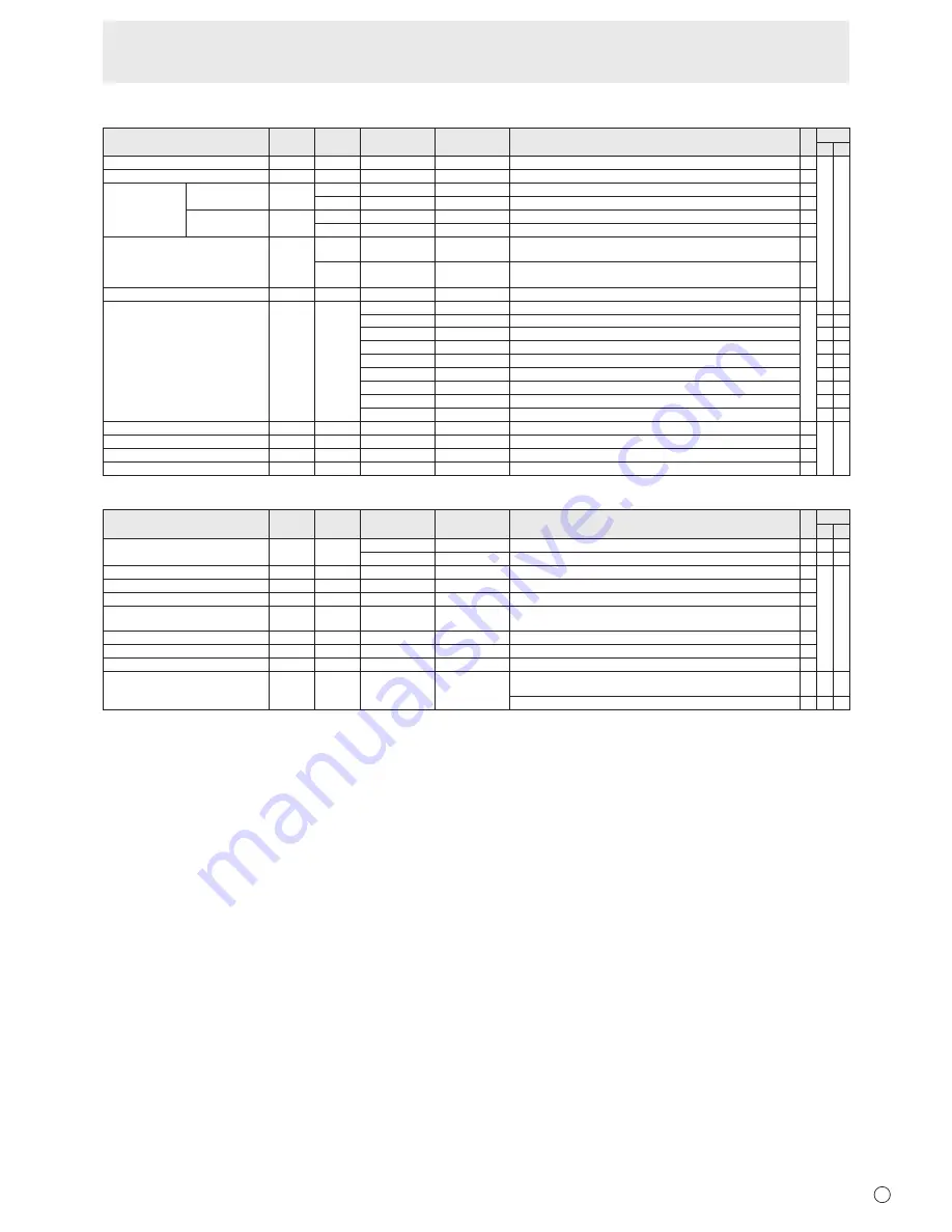
PIP/PbyP menu

Function

Command Direction

Parameter

Reply

Control/Response contents

*1

*2

(A) (B)

PIP MODES

MWIN

WR

0-3

0-3 0: OFF, 1: PIP, 2: PbyP, 3: PbyP2

○ ○

PIP SIZE

MPSZ

WR

1-64

1-64

PIP POS

THE LONGEST 
DIRECTION

MHPS

W

0-100

R

0-100

THE SHORTEST 
DIRECTION

MVPS

W

0-100

R

0-100

PIP POS LD+SD BATCH

MPOS

W

0-100,0-100

Specify the position in MPOSxxxyyy format. 
(xxx: Longer side, yyy: Shorter side position)

R

0-100,0-100

Returns a response in (xxx,yyy) format. 
(xxx: Longer side, yyy: Shorter side position)

PIP BLEND

MWBL

WR

0-15

0-15

PIP SOURCE

MWIP

WR

1

1 PC DVI-D

-

2

2

PC D-SUB

○ ○

3

3

AV COMPONENT

-

4

4

AV VIDEO

-

6

6

PC RGB

-

7

7

AV DVI-D

-

8

8

AV S-VIDEO

-

9

9

AV HDMI

○ ○

10

10 PC HDMI

-

SOUND CHANGE

MWAD

WR

1-2

1-2 1: MAIN, 2: SUB

○ ○

MAIN POS (Main screen)

MWPP

WR

0-1

0-1 0: POS1, 1: POS2

PbyP2 POS (Sub screen)

MW2P

WR

0-2

0-2 0: POS1, 1: POS2, 2: POS3

AUTO OFF

MOFF

WR

0-1

0-1 0: MANUAL, 1: AUTO

Initialization/Functional Restriction Setting (FUNCTION) menu

Function

Command Direction

Parameter

Reply

Control/Response contents

*1

*2

(A) (B)

ALL RESET

RSET

W

0

0: ALL RESET

-

-

0-1

0: ALL RESET 1, 1: ALL RESET 2

-

-

ADJUSTMENT LOCK

ALCK

WR

0-2

0-2 0: OFF, 1:ON1, 2:ON2

○ ○

ADJUSTMENT LOCK TARGET

ALTG

WR

0-2

0-2 0: REMOTE CONTROL, 1: MONITOR BUTTONS, 2: BOTH

OSD DISPLAY

LOSD

WR

0-2

0-2 0: ON1, 1: OFF, 2: ON2

LED

OFLD

WR

0-1

0-1 0: ON, 1: OFF

“ERR” when LOW POWER is selected for STANDBY MODE.

TEMPERATURE ALERT

TALT

WR

0-2

0-2 0: OFF, 1: OSD & LED, 2: LED

STATUS ALERT

SALT

WR

0-2

0-2 0: OFF, 1: OSD & LED, 2: LED

POWER BUTTON

PBTN

WR

0-1

0-1 0: MONITOR, 1: CONTROLLER

CONTROLLER INPUT

PCIP

WR

0-2

0-2 0: D-SUB, 1: HDMI (“ERR” when MONITOR is selected for POWER 

BUTTON.)

○ ○ ○

2: DVI-D (“ERR” when MONITOR is selected for POWER BUTTON.)

-

Controlling the Monitor with a PC (RS-232C)

Summary of Contents for PN-V600A

Page 1: ...PN V600A LCD MONITOR OPERATION MANUAL ...

Page 2: ...d with the coloured markings identifying the terminals in your plug proceed as follows The wire which is coloured GREEN AND YELLOW must be connected to the terminal in the plug which is marked by the letter E or by the safety earth or coloured green or green and yellow The wire which is coloured BLUE must be connected to the terminal which is marked with the letter N or coloured black The wire whi...

Page 3: ...tions to this equipment not expressly approved by the manufacturer could void the user s authority to operate this equipment NOTE This equipment has been tested and found to comply with the limits for Class A digital device pursuant to Part 15 of the FCC Rules These limits are designed to provide reasonable protection against harmful interference when the equipment is operated in a commercial envi...

Page 4: ...cal authorities or dealer and ask for the correct method of disposal ONLY FOR USERS IN THE EUROPEAN UNION AND SOME OTHER COUNTRIES FOR INSTANCE NORWAY AND SWITZERLAND Your participation in separate collection is requested by law The symbol shown above appears on electrical and electronic equipment and batteries or the packaging to remind users of this If Hg or Pb appears below the symbol this mean...

Page 5: ... or objects from resting on them 10 The LCD panel used in this product is made of glass Therefore it can break when the product is dropped or applied with impact Be careful not to be injured by broken glass pieces in case the LCD panel breaks 11 Overloading Do not overload AC outlets or extension cords Overloading can cause fire or electric shock 12 Entering of objects and liquids Never insert an ...

Page 6: ...nvironment this product may cause radio interference in which case the user may be required to take adequate measures To maintain compliance with EMC regulations use shielded cables to connect to the following terminals PC AV DVI D output terminal PC AV DVI D input terminal PC AV HDMI input terminal PC D SUB input terminal PC RGB input terminals and RS 232C input output terminals If a monitor is n...

Page 7: ... fire or malfunction Please request a cleaning of the inside of the monitor from an authorized SHARP servicing dealer or service center Images cannot be rotated on this monitor When using in portrait orientation you will need to prepare appropriately orientated content in advance The AC outlet shall be installed near the equipment and shall be easily accessible The Power Cord Use only the power co...

Page 8: ...e monitor inside a housing or if the ambient temperature may be outside of the range of 32ºF 0ºC to 104ºF 40ºC install a fan or take other measures to keep the ambient temperature within the required range Temperature condition may change when using the monitor together with the optional equipments recommended by SHARP In such cases please check the temperature condition specified by the optional ...

Page 9: ...12 Multiple monitor connection 13 Preparing the Remote Control Unit 15 Installing the batteries 15 Remote control operation range 15 Connecting the Power Cord 15 Binding Cables 16 Removing the Handles 16 Affixing the Protection Covers 16 Turning Power On Off 17 Turning on the main power 17 Turning power on off 17 Disabling power on off operations 17 Basic Operation 18 Remote Control Mode 21 Menu I...

Page 10: ...ll be released 15 AC input terminal 16 Main power switch 17 PC AV HDMI input terminal 18 PC D sub input terminal 19 Audio input terminal 20 Audio output terminals 21 RS 232C output terminal 22 RS 232C input terminal 23 Optional terminal This terminal is provided for possible future optional function expansion Offering of this terminal is not a guarantee that future expanded functionality will be p...

Page 11: ...n 4 VOL Cursor control button 5 BRIGHT Cursor control button 6 DISPLAY button 7 MODE button 8 INPUT button 9 MENU button 10 BRIGHT Cursor control button 11 VOL Cursor control button 12 SIZE button n Remote control sensor box Supplied with the PN ZR01 optional 1 2 3 4 1 Brightness sensor 2 Remote control sensor 3 Connection cable 4 Mounting bracket ...

Page 12: ...erminal Use a commercially available HDMI cable conforming to the HDMI standard Set HDMI of INPUT SELECT on the OPTION menu according to the device to be connected Select the audio input terminal to be used in PC HDMI or AV HDMI of AUDIO SELECT on the OPTION menu When HDMI is selected connection to the audio input terminal is unnecessary 2 PC D sub input terminal When the PN ZB02 optional is attac...

Page 13: ...ION menu to PC RGB when using the PC RGB input terminals Select the audio input terminal to be used in PC RGB of AUDIO SELECT on the OPTION menu 15 AV component input terminals Set BNC of INPUT SELECT on the OPTION menu to AV COMPONENT when using the AV component input terminals Select the audio input terminal to be used in AV COMPONENT of AUDIO SELECT on the OPTION menu 16 AV video input terminal...

Page 14: ...ors together in a daisy chain with RS 232 cable Attach the remote control sensor box as shown in the following illustration When attached to the left side because the top and bottom for the remote control sensor box will be reversed the connection cable will be on top the right side is recommended Caution When attaching the remote control sensor box turn the main power switch OFF Except for the re...

Page 15: ...emote control unit is approx 23 feet 7 m when aimed directly at the remote control sensor box When used at an angle of approx 10 from the center to the top bottom right left of the remote control sensor use it within a distance of approx 16 4 feet 5 m Remote control sensor 10º 10º 16 4 feet 5 m 16 4 feet 5 m 23 0 feet 7 m 23 0 feet 7 m TIPS Do not expose the remote control unit to shock by droppin...

Page 16: ...e handles and handle spacers in order and secure Caution The handles handle screws and handle spacers are for this monitor Do not use them for any other devices When attaching the handles always use this monitor s handles handle spacers and handle screws Be sure the handles are attached securely TIPS To lower the height of the handles attach the handles with the handle spacers removed To attach th...

Page 17: ...ge 25 If you change the remote control mode to ALL MONITORS power can be turned ON OFF for all secondary monitors connected with RS 232 cable For operation with the monitor buttons use the buttons on the primary monitor nDate time setting If the time has yet to be set when the monitor is first turned on the date time setting screen appears Set the date and time DATE TIME SETTING SET CANCEL OK MENU...

Page 18: ...AV DVI D input terminal 3 2 PC HDMI PC AV HDMI input terminal 1 PC D SUB PC D sub input terminal PC RGB PC RGB input terminals 4 AV DVI D PC AV DVI D input terminal 3 AV HDMI PC AV HDMI input terminal 1 AV COMPONENT AV component input terminals 4 AV S VIDEO AV S video input terminal AV VIDEO AV video input terminal 1 Select the terminal to be used in HDMI of INPUT SELECT See page 26 2 Select the t...

Page 19: ...ION1 INFORMATION2 clear display and so on every time you press this button The display disappears automatically after about 15 seconds LAN is displayed during LAN communication If LAN is displayed in red there is a duplicate IP address If using the monitor buttons press under INFORMATION in the OPTION menu 8 MODE Color mode selection Each time you press this button the color mode changes in the fo...

Page 20: ...lay functions to compress or expand the screen for commercial or public viewing in establishments like cafes or hotels may infringe on the rights of the creators as protected by Copyright Law so please be careful When Enlarge is set the screen size is fixed to WIDE mode When dual screen display is selected the screen size cannot be changed The appearance of the original video may change if you sel...

Page 21: ...d input mode selection operation Settings may not be reflected depending on the state of the connected monitors Example If the power for the primary is turned ON the power for all the monitors will be turned ON Secondary ID No 2 Secondary ID No 3 Primary ID No 1 Secondary ID No 4 Power ON Power ON Power ON Power ON Press to turn the power ON POWER Press or to select EXPAND ITEM and press or to sel...

Page 22: ...RE AUDIO SETUP OPTION MULTI PIP PbyP OK MENU MOVE OSD DISPLAY 1 3 6 6 x 7 6 8 V 60 Hz H 47 7 kHz For items that have press make settings and then press MENU 5 Press MENU twice to close the menu screen TIPS The menu will differ depending on the input mode The menu screen will close automatically if no operation is performed for about 15 seconds DATE TIME SETTING SCHEDULE and LAN SETUP screens will ...

Page 23: ...s MENU nPICTURE You can move the menu screen display position each time DISPLAY is pressed AUTO PC D SUB PC RGB The ANALOG GAIN and ANALOG OFFSET are automatically adjusted Pressing performs adjustment ANALOG GAIN PC D SUB PC RGB Adjusts the bright portions of the video input signal ANALOG OFFSET PC D SUB PC RGB Adjusts the dark portions of the video input signal BRIGHT Adjusts the backlight brigh...

Page 24: ...nd horizontally PATTERN2 A black screen spreads from the bottom of the screen and then shrinks to the bottom of the screen If the monitor is installed in the portrait orientation a black screen spreads from the left end of the screen and then shrinks to the left end of the screen PATTERN3 A black bar moves from the left end to the right end of the screen If the monitor is installed in the portrait...

Page 25: ...AV HDMI and PC AV DVI D input terminals RS 232C LAN SELECT Selects the method with which to control the monitor from the computer ID No SET Assigns ID numbers to monitors connected in a daisy chain see page 34 using the RS 232 cables The numbers 1 to 255 are available for ID numbers If 0 is set the system regards this as the state where no ID number is set AUTO ASSIGN ID No ID No to be used will b...

Page 26: ...terminals When set to VARIABLE2 audio is not output from the external speaker terminals VARIABLE You can adjust the volume using VOLUME FIXED Disables volume adjustment and fixes the sounds When the PN ZB02 optional is attached VARIABLE1 You can adjust the volume using VOLUME VARIABLE2 You can adjust the volume using VOLUME but audio is not output from the external speaker terminals FIXED Disables...

Page 27: ... PIP mode PIP V POS Adjusts the vertical position of the sub screen in PIP mode PIP BLEND In PIP mode use this menu item to display the sub screen transparently PIP SOURCE Selects the input signal of the sub screen in PIP PbyP or PbyP2 mode SOUND CHANGE Sets the sound which is output in PIP PbyP or PbyP2 mode If the main screen is displayed as a full screen by the AUTO OFF function the sound for t...

Page 28: ...al screen display is selected the SCREEN MOTION function is disabled When dual screen display is selected the AUTO INPUT CHANGE function is disabled When dual screen display is selected the screen cannot be enlarged When dual screen display is selected the INPUT SELECT options cannot be set When an interlaced signal 1080i 480i video S Video is input to the sub screen horizontal lines may flicker I...

Page 29: ...execute the SCHEDULE 0 ONLY ONCE Executes the SCHEDULE once on the specified day Specify the day of the week to execute the SCHEDULE 1 EVERY WEEK Executes the SCHEDULE on the specified day of the week every week Specify the day of the week to execute the SCHEDULE Periodic setting such as Monday through Friday is also possible 2 EVERY DAY Executes the SCHEDULE every day regardless of the day of the...

Page 30: ... to PC RGB and display the adjustment pattern See the description below 2 Press MENU and use or to display the SCREEN menu 3 Press and select AUTO 4 Press The automatic adjustment is complete in several seconds 5 Press MENU twice to close the menu screen TIPS If the screen cannot be adjusted properly with one automatic adjustment repeat the automatic adjustment two or three times Try manual adjust...

Page 31: ... Prohibits remote control and monitor button operation Initialization Reset Functional Restriction Setting FUNCTION RS 232C RS 232C LAN when the PN ZB02 optional is attached Specifies whether to allow control via RS 232C or LAN see pages 32 and 45 OSD DISPLAY Shows hides the menu modes and messages The FUNCTION and REMOTE CONTROL MODE screens cannot be hidden ON 1 Shows all menus modes and message...

Page 32: ... RS 232C input terminal RS 232C output terminal Communication conditions Set the RS 232C communication settings on the PC to match the monitor s communication settings as follows Baud rate Stop bit 1 bit Data length 8 bits Flow control None Parity bit None Set to the same baud rate as the BAUD RATE setting of SETUP menu Initial setting 38400 bps When connecting multiple monitors in a daisy chain s...

Page 33: ...ands are used WAIT is returned In this case a value will be returned if you wait a while Do not send any command during this period No ID number is attached to WAIT response Commands which return WAIT 1 When repeater control is used 2 When an IDSL or IDLK command is used 3 When one of the following commands is used RSET INPS ASNC WIDE EMAG EPOS PXSL POWR AGIN MWIN MWIP MWPP ESTG EMHV EPHV ESHV ENL...

Page 34: ...D number 1 ID number 2 ID number 3 ID number 4 IDST A monitor receiving this command sets its own ID number in the parameter field Example IDST0001 OK 001 The ID number of this monitor is set to 1 TIPS You can automatically assign ID numbers by using the IDST command with the Repeater control see Repeater control on page 35 For example using the command IDST001 automatically sets the ID numbers as...

Page 35: ...ns effective until it is canceled or power is shut off IDCK Provides screen display of the ID number currently assigned to a monitor and the ID number currently set for IDLK if any Example After executing IDLK0002 IDCK0000 Parameter has no meaning ID 001 IDLK 002 Returned response The ID number is also displayed on the monitor screen IDCK000 Repeater control If a command is used with repeater cont...

Page 36: ... C2 C3 C4 P1 P2 P3 P4 S1 S2 Command field Block number 01 to 16 Data field Checksum field Example To transfer the data of block 1 0 to 31 levels of red R data UGRW01000000010002 0031C0 Command Block number 32 pieces of data Checksum One piece of data consists of 4 digits If data is less than 4 digits add a 0 zero to make it 4 digits The checksum field is the character string ASCII data of lower or...

Page 37: ...hen PN ZB02 optional is attached The command can be used Error ERR Power control Input mode selection Function Command Direction Parameter Reply Control Response contents 1 2 A B POWER CONTROL POWR W 0 Switches to standby mode 1 Returns from standby mode R 0 Standby mode 1 Normal mode 2 Input signal waiting mode INPUT MODE SELECTION INPS W 0 Toggle change for input mode Terminals not selected in I...

Page 38: ...0 100 0 800 on PC D SUB PC RGB Varies depending on the signal Position of the shortest direction VPOS WR 0 100 0 100 0 200 on PC D SUB PC RGB Varies depending on the signal size SIZE of the longest direction HSIZ WR 0 100 0 100 SIZE of the shortest direction VSIZ WR 0 100 0 100 RESOLUTION Longest direction resolution HRES WR 300 1920 300 1920 When the input mode is PC D SUB PC RGB Only even number...

Page 39: ... W 2 Resets the saturation C M S VALUE CMVR WR 10 10 10 10 R CMVY Y CMVG G CMVC C CMVB B CMVM M CRST W 3 Resets the brightness COLOR MODE BMOD WR 0 0 STD 2 2 VIVID 3 3 sRGB When the input mode is PC 4 4 HIGH ILLUMINANCE WHITE BALANCE THRU CTMP WR 0 0 When the input mode is PC DVI D PC HDMI PRESET 1 18 1 18 From 1 approximately 3 000K to 15 approximately 10 000K 500K steps 16 approximately 5 600K 1...

Page 40: ...E IDSL W 1 255 Sets a monitor ID number This ID number is only effective for the command immediately after this command 0 Clears the ID number if one has been designated ID NO SETTING SUBSEQUENT IDLK W 1 255 Sets a monitor ID number This ID number is effective for the next and all subsequent commands after this command 0 Clears the ID number if one has been designated ID CHECK IDCK W 0 ID xxx IDLK...

Page 41: ...AUDIO STEREO MINI 2 3 2 3 2 AUDIO1 RCA 3 AUDIO2 RCA PC RGB ASCP WR 1 3 1 3 1 AUDIO STEREO MINI 2 AUDIO1 RCA 3 AUDIO2 RCA AV DVI D ASDA WR 1 3 1 3 1 AUDIO STEREO MINI 2 AUDIO1 RCA 3 AUDIO2 RCA AV HDMI ASHA WR 0 1 0 1 0 HDMI 1 AUDIO STEREO MINI 2 3 2 3 2 AUDIO1 RCA 3 AUDIO2 RCA AV COMPONENT ASCA WR 1 3 1 3 1 AUDIO STEREO MINI 2 AUDIO1 RCA 3 AUDIO2 RCA AV S VIDEO ASSA WR 1 3 1 3 1 AUDIO STEREO MINI 2...

Page 42: ...MODE setting and the IMAGE POSITION THE SHORTEST DIRECTION EPSV WR 999 999 999 999 BEZEL ADJUST BZCO WR 0 1 0 1 0 OFF 1 ON BEZEL ADJUST TOP BZCT WR 0 1 0 1 0 OFF 1 ON BOTTOM BZCB WR 0 1 0 1 0 OFF 1 ON RIGHT BZCR WR 0 1 0 1 0 OFF 1 ON LEFT BZCL WR 0 1 0 1 0 OFF 1 ON BEZEL WIDTH TOP BZWT WR 0 100 0 100 BOTTOM BZWB WR 0 100 0 100 RIGHT BZWR WR 0 100 0 100 LEFT BZWL WR 0 100 0 100 ENLARGE IMAGE POSITI...

Page 43: ... 0 1 0 1 0 POS1 1 POS2 PbyP2 POS Sub screen MW2P WR 0 2 0 2 0 POS1 1 POS2 2 POS3 AUTO OFF MOFF WR 0 1 0 1 0 MANUAL 1 AUTO Initialization Functional Restriction Setting FUNCTION menu Function Command Direction Parameter Reply Control Response contents 1 2 A B ALL RESET RSET W 0 0 ALL RESET 0 1 0 ALL RESET 1 1 ALL RESET 2 ADJUSTMENT LOCK ALCK WR 0 2 0 2 0 OFF 1 ON1 2 ON2 ADJUSTMENT LOCK TARGET ALTG ...

Page 44: ...emperature sensor abnormality when 126 is returned CAUSE OF LAST STANDBY MODE STCA W 0 Initialization R 0 No detectable error has occurred 1 Standby mode by POWER button 2 Main power off by the main power switch 3 Standby mode by RS 232C or LAN 4 Input signal waiting mode by No Signal 6 Standby mode by abnormal temperature 8 Standby mode by SCHEDULE setting 20 Standby mode by OFF IF NO OPERATION s...

Page 45: ... LAN Settings to connect to a LAN Set the monitor s IP address and subnet mask to match the settings of your LAN These settings can be made on either the monitor or a PC connected to the monitor The settings depend on the configuration of your LAN Ask your LAN administrator for details To set on the monitor Set RS 232C LAN SELECT on the SETUP menu to LAN and then set the LAN SETUP options See page...

Page 46: ...rent IP address subnet mask and default gateway settings Make sure you write this information now as you will be changing the IP address subnet mask and default gateway settings back to these settings afterwards 7 Temporarily change the IP address and subnet mask To access the monitor as it is shipped from the factory set as follows IP Address 192 168 150 1 Subnet Mask 255 255 255 0 Default Gatewa...

Page 47: ...5 Controlling with a PC Basic operation You use Internet Explorer on a PC on the LAN to control the monitor 1 Launch Internet Explorer on the PC 2 In the Address box type http followed by your monitor s IP address followed by then press the Enter key You can confirm the IP address with the DISPLAY function When prompted to enter a user name and password type the user name and password that you spe...

Page 48: ...ilable ADJUSTMENT You can adjust these settings which are also available on the monitor s menu SCREEN See page 23 PICTURE See page 23 PICTURE ADVANCED See page 30 AUDIO See page 24 SETUP See page 24 OPTION See page 26 SCHEDULE See page 29 MULTI See page 27 PIP PbyP See page 27 FUNCTION See page 31 TIPS After changing DISPLAY COLOR PATTERN to OFF click Refresh to correctly retrieve the status of th...

Page 49: ...tting TIPS When manually setting the IP address the IP address for secondary monitors connected by RS 232C can be automatically allocated See page 25 NETWORK SECURITY This screen allows you to specify the security related settings USER NAME PASSWORD Sets up a user name and password to restrict access to this monitor After entering a user name and password click Apply ACCEPT IP ADDRESS You can limi...

Page 50: ...NATOR This screen allows you to configure the e mail sent periodically or when the monitor has an error The settings depend on the configuration of your LAN Ask your LAN administrator for details SMTP SERVER Specify the SMTP server address for sending e mail When using a domain name make sure to specify the DNS SERVER as well See page 49 ORIGINATOR E MAIL ADDRESS Specify the e mail address for thi...

Page 51: ...mail which notifies a temperature or status error TIPS The RECIPIENT E MAIL ADDRESSES can be up to 64 alphanumeric characters or symbols Controlling the Monitor with a PC LAN MAIL PERIODICAL When PERIODICAL for CONDITION of MAIL RECIPIENT is checked set the date and time to send the mail DAY OF THE WEEK Specify the day of the week to send the periodical mails TIME Specify the time of the day to se...

Page 52: ...main power switch When the monitor restarts wait about 30 seconds and then start the next operation If the IP address is changed while the SNMP function is operational turn off the monitor and then turn it on again with the main power switch TIPS Depending on the SNMP settings a short delay may occur before the SNMP is usable About 2 minutes Up to 16 alphanumeric letters and symbols can be used fo...

Page 53: ...See pages 57 to 58 The video from the PC AV DVI D input terminal does not appear properly Is the setting for DVI of INPUT SELECT on the OPTION menu correct See page 26 Is the input signal compatible with this monitor See pages 57 to 58 Turn off the power to the connected equipment and then turn the power on again If the monitors are connected in a daisy chain turn off the power to all the monitors...

Page 54: ...utomatically enters standby mode The Power LED continues flashing red and green alternately Remove the cause of the excessive temperature rise If the monitor enters standby mode due to a rise in temperature to return to normal display turn the power switch off and then back on again The monitor however will enter standby mode again if the cause of the temperature rise is not eliminated Check wheth...

Page 55: ...nal is attached 10 BASE T 100 BASE TX Power requirement AC 100 V 240 V 50 60 Hz Operating temperature 3 32 F to 104 F 0 C to 40 C Operating humidity 20 to 80 no condensation Power consumption maximum input signal waiting mode 4 standby mode 5 305 W 1 0 W 1 0 W Power consumption PN ZB02 optional 310 W Dimensions excluding protrusions inch mm Approx 52 5 8 W x 5 7 8 D x 29 11 16 H 1335 9 x 149 3 x 7...

Page 56: ...f the monitor nPower management This monitor conforms to VESA DPMS and DVI DMPM Both your video card and computer must support the same standard in order for the monitor s power management function to work DPMS Display Power Management Signaling DPMS Screen Power consumption 1 Hsync Vsync ON STATE Display 305 W Yes Yes STANDBY No display 1 0 W 2 No Yes SUSPEND Yes No OFF STATE No No 1 When PN ZB02...

Page 57: ... 0MHz 49 5MHz 33 75MHz 65 0MHz 75 0MHz 78 75MHz 108 0MHz 79 5MHz 102 25MHz 83 5MHz 108 0MHz 108 0MHz 135 0MHz 85 5MHz 121 75MHz 106 5MHz 162 0MHz 146 25MHz 74 4MHz 85 383MHz 148 5MHz 148 5MHz 28 3MHz 64 13MHz 70 4MHz 74 25MHz 94 88MHz 108 23MHz 117 01MHz 134 99MHz 135 76MHz Yes Yes Yes Yes Yes Yes Yes Yes Yes Yes Yes Yes Yes Yes Yes Yes Yes Yes Yes Yes Yes Yes Yes Yes Yes Yes Yes Analog D SUB RGB ...

Page 58: ...1280 720p 50Hz Yes Yes Yes 59 94Hz Yes Yes Yes 60Hz Yes Yes Yes 720 576p 50Hz Yes Yes Yes 720 480p 59 94Hz Yes Yes Yes 60Hz Yes Yes Yes 640 480p VGA 59 94Hz Yes Yes 60Hz Yes Yes 720 1440 576i 50Hz Yes Yes 720 1440 480i 59 94Hz Yes Yes 60Hz Yes Yes 1 Displays a reduced image except in Dot by Dot In Dot by Dot the image will be cut down to panel size then displayed 2 Available when the PN ZB02 optio...

Page 59: ...VI D 24 pin No Function No Function 1 TMDS data 2 13 N C 2 TMDS data 2 14 5V 3 TMDS data 2 4 shield 15 GND 4 N C 16 Hot plug detection 5 N C 17 TMDS data 0 6 DDC clock 18 TMDS data 0 7 DDC data 19 TMDS data 0 5 shield 8 N C 20 N C 9 TMDS data 1 21 N C 10 TMDS data 1 22 TMDS clock shield 11 TMDS data 1 3 shield 23 TMDS clock 12 N C 24 TMDS clock nPC AV HDMI input terminal pins HDMITM Connector No F...

Page 60: ...more the weight of the monitor Install by the most suitable method for the material and the structure To attach a VESA compliant mounting bracket use M6 screws that are 5 16 inch 8 mm to 3 8 inch 10 mm longer than the thickness of the mounting bracket When moving the monitor be sure to hold it with either handles or the corners on the bottom of the unit Do not hold the LCD panel This may cause pro...

Page 61: ...PN V600A Mu EN13J 1 ...

Reviews: