background image

40

E

TIPS

•  You might infringe on a copyright of the author which is 

protected by copyright law when you display the images of 

the computer screen and television/VCR simultaneously for 

profit-making or to show the image to the public.

•  When quad-screen display is selected, screen size cannot 

be changed. 

The screen size for quad-screen display is the same as 

the screen size for single-screen display. The Dot by Dot 

screen is displayed in NORMAL size.

•  When quad-screen display is selected, the CONNECT 

AUTO INPUT SELECT function and NO SIGNAL AUTO 

INPUT SEL. function are disabled.

•  When quad-screen display is selected, D-SUB of INPUT 

SELECT cannot be set.

•  When quad-screen display is selected, SCREEN menu and 

AUDIO menu cannot be set.

•  When quad-screen display is selected, the DISPLAY 

COLOR PATTERN cannot be set.

•  When the screen size is set to ZOOM2 and ZOOM2 

SPECIAL SETTING is set to ON, that display state is held.

•  When quad-screen display is selected, DisplayPort2 of 

DisplayPort STREAM cannot be set.

•  When quad-screen display is selected, the monitor will 

not enter the input signal waiting mode when POWER 

MANAGEMENT is set to ON.

•  When quad-screen display is selected, HDMI CEC LINK 

does not operate.

•  When quad-screen display is selected, the FREEZE, DP 

(DisplayPort), HDMI, and OPTION buttons cannot be used.

•  When quad-screen display is selected, the position 1 

screen is output from the DisplayPort output terminal.

•  When quad-screen display is selected, the connected 

computer cannot be operated by touch.

n

ZOOM2 SPECIAL SETTING

If you connect a laptop computer with any of the following 

screen resolutions and black bands appear around the screen, 

set ZOOM2 SPECIAL SETTING of INPUT SIGNAL on the 

OTHERS menu to ON and then select ZOOM2 in the SIZE 

setting.

This displays the area inside the black band.

Laptop computer 

resolution

Corresponding signal*

1

1280x800

1280x1024, 1280x960, 1400x1050*

2

1280x600

1280x720

1024x600

1024x768

*1:  This setting is effective only when the screen resolution, 

including the black band, is one of the resolutions listed 

above.

*2:  Use the automatic screen adjustment.

Menu Items

n

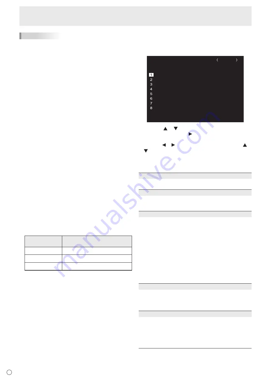
SCHEDULE

You can set the time to switch the monitor on and off.

Set this function with “SCHEDULE” in the SETUP menu. (See 

page 34.)

-

:

– –

– –

– –

– –

– –

– –

SCHEDULE

No.

POWER

DAY OF THE WEEK

TIME

INPUT

BRIGHT

– –/– –/– – – –      – – –            – –:– –:– –

D-SUB[RGB]

(1)

-

:

– –

– –

– –

– –

– –

– –

-

:

– –

– –

– –

– –

– –

– –

-

:

– –

– –

– –

– –

– –

– –

-

:

– –

– –

– –

– –

– –

– –

-

:

– –

– –

– –

– –

– –

– –

-

:

– –

– –

– –

– –

– –

– –

-

:

– –

– –

– –

– –

– –
– –
– –
– –
– –
– –
– –
– –

– –

– –

(5)

(2)

(3)

(4)

(6)

OK:[ENTER]  CANCEL:[RETURN]

1.  Press the   or   button to select the SCHEDULE 

number, and press the 

 button.

2.  Set the SCHEDULE.

 (See the description below.)

Press the   or   button to select items, and press the   or 

 button to change the setting.

3.  Press the ENTER button.

SCHEDULE becomes effective.

(1)

●: SCHEDULE effective

-: SCHEDULE not effective

(2) POWER

ON  :  Switches the monitor on at the specified time.

OFF :  Switches the monitor off at the specified time and puts 

the monitor in standby mode.

(3) DAY OF THE WEEK

Specifies the day of the week to execute the SCHEDULE.

0:ONLY ONCE

Executes the SCHEDULE once on the specified day.

Specify the day of the week to execute the SCHEDULE.

1:EVERY WEEK

Executes the SCHEDULE on the specified day of the week 

every week. Specify the day of the week to execute the 

SCHEDULE. 

Periodic setting such as “Monday through Friday” is also 

possible.

2:EVERY DAY

Executes the SCHEDULE every day regardless of the day 

of the week.

(4) TIME

Specifies the time to execute the SCHEDULE.

Set the time on a 24-hour basis. (Factory default)

Can be entered as 12-hour time using the TIME setting in 

DATE/TIME FORMAT.

(5) INPUT

Specifies the input mode at power-on. If not specified, the 

START INPUT MODE setting will apply. By factory default, 

the input that was active when the power was last turned off 

will appear.

Input modes displayed on D-SUB will depend upon the 

INPUT SELECT settings.

Summary of Contents for PN-70TH5

Page 1: ...PN 70TH5 LCD MONITOR OPERATION MANUAL ...

Page 2: ... dealer and ask for the correct method of disposal ONLY FOR USERS IN THE EUROPEAN UNION AND SOME OTHER COUNTRIES FOR INSTANCE NORWAY AND SWITZERLAND Your participation in separate collection is requested by law The symbol shown above appears on electrical and electronic equipment and batteries or the packaging to remind users of this If Hg or Pb appears below the symbol this means that the battery...

Page 3: ... literature accompanying the product FOR CUSTOMERS IN U K IMPORTANT The wires in this mains lead are coloured in accordance with the following code GREEN AND YELLOW Earth BLUE Neutral BROWN Live As the colours of the wires in the mains lead of this apparatus may not correspond with the coloured markings identifying the terminals in your plug proceed as follows The wire which is coloured GREEN AND ...

Page 4: ...t people from stepping on them or objects from resting on them 10 The screen used in this product is made of glass Therefore it can break when the product is dropped or applied with impact Be careful not to be injured by broken glass pieces in case the screen breaks 11 Overloading Do not overload power outlets or extension cords Overloading can cause fire or electric shock 12 Entering of objects a...

Page 5: ...the user may be required to take adequate measures An apparatus with CLASS I construction shall be connected to a MAIN socket outlet with a protective earthing connection To maintain compliance with EMC regulations use shielded cables to connect to the following terminals HDMI input terminal D SUB input terminal DisplayPort input output terminals and RS 232C input terminal If a monitor is not posi...

Page 6: ...ointed object such as a fingernail or pencil Depending on the application used the touch pen may not function If another USB device is connected to the computer to which the touch panel is connected do not operate the USB device during touch panel input Input may not take place correctly Do not allow a cable to come near the screen This may cause the touch panel to malfunction The Power Cord Use o...

Page 7: ...s could lead to a malfunction Do not place the monitor on a device which generates heat Adhere to the following when installing the monitor in its portrait orientation Failing to adhere to the following may cause malfunctions Install the monitor such that the power LED is located on the bottom side Power LED Set the PORTRAIT LANDSCAPE INSTALL on the MONITOR menu to PORTRAIT See page 36 Be sure to ...

Page 8: ...ch Pen Preparations 19 Computer preparations 19 Touch pen actions 20 Adding touch pens pairing 21 Touch action 22 Touch action 22 Other functions 24 Cautionary points 24 Eraser 24 Basic Operation 25 Using the touch menu 25 Using the remote control unit 26 Menu Items 29 Displaying the menu screen 29 Configuring settings in the touch menu 30 Menu item details 31 Adjustments for computer screen displ...

Page 9: ...ws supplied with this monitor is used CPU Intel Core i5 6360U or faster Intel Core i7 6650U or faster recommended Video Output Must be capable of output at a Vsync of 60 Hz or higher Memory At least 4 GB Free space on hard drive At least 5 GB free space separately required for data storage To use the touch panel the touch panel and computer must be connected and Touch pen Management Tool and Pen S...

Page 10: ...fering of this terminal is not a guarantee that future expanded functionality will be released 18 RS 232C input terminal See page 13 19 Touch pen adapter port See page 19 20 USB port See page 13 21 USB 1 port for touch panel See page 13 22 DisplayPort output terminal See page 13 23 HDMI 1 input terminal See page 12 24 DisplayPort 1 input terminal See page 12 25 Audio input terminal See page 12 26 ...

Page 11: ...11 E Part Names nRemote control unit 1 2 1 Signal transmitter 2 Operation buttons See page 26 ...

Page 12: ...devices The audio input terminals used in each input mode are factory set as follows Input mode Audio input terminal Factory setting HDMI1 HDMI 1 input terminal HDMI2 HDMI 2 input terminal HDMI3 HDMI 3 input terminal DisplayPort 1 DisplayPort 1 input terminal DisplayPort 2 DisplayPort 2 input terminal D SUB Audio input terminal It is convenient to use the terminals for separate purposes For exampl...

Page 13: ...l to the computer with a USB cable Factory setting Can be changed in TOUCH INPUT SELECT on the SETUP menu D sub input terminal DisplayPort 2 input terminal HDMI 2 input terminal HDMI 3 input terminal 13 USB port Use to connect a device when using Pen Software multi board mode optional To build a system consult your dealer 14 RS 232C input terminal The monitor can be connected to a computer using t...

Page 14: ...er cord supplied into the power outlet Binding Cables Main power switch 1 AC input terminal 2 Power cord Supplied For power outlet 3 Cable Cable clamp insertion type 1 2 Cable clamp Cable Cable clamp attachment Cable clamp attachment 2 1 1 1 1 2 1 2 1 The cables connected to the terminals on the rear of the monitor and the USB cable on the back of the tray can be fastened with the cable clamp ...

Page 15: ...oper operation Replace the batteries when they run low as this may shorten the remote control s operation range If a fluorescent light is illuminated near the remote control unit it may interfere with proper operation Do not use it with the remote control of other equipment such as air conditioner stereo components etc Installing the batteries 1 Place your finger on the part marked with the and th...

Page 16: ...he handles are attached securely 2 1 1 2 It is possible to mount a commercially available web camera in the following positions 1 Attach the supplied camera mount with the supplied camera mount screws x2 2 Attach the web camera commercially available to the camera mount with the supplied camera screw inch thread x1 1 The camera mount cannot be attached when the tray is attached To attach the camer...

Page 17: ...er off Standby mode Blue flashing Input signal waiting mode TIPS You can fix the input mode that appears after startup Set START INPUT MODE on the SETUP menu Turning Power On Off Turning power off Turning power off with monitor buttons POWER button 1 Touch the POWER button The recognition screen appears 2 Touch OK The power is turned off Standby mode TIPS If about 15 seconds elapses while the reco...

Page 18: ...n appears Set the date and time DATE TIME SETTING OK ENTER CANCEL RETURN 01 01 17 00 00 20 1 Press the or button to select the date and time and press the or button to change the numerical values 2 Press the ENTER button Be sure to set the date and time The date time setting screen will close automatically if no operation is performed for about 15 seconds The date and time can be set using DATE TI...

Page 19: ...ery LR 03 AAA size x 1 into the touch pen Check the plus and minus markings on the inside of the touch pen and insert the battery in the correct orientation Battery cover 3 Replace the battery cover and main cover While pressing the battery cover replace the main cover 1 2 4 Replace the battery cap 2 1 TIPS Life of supplied battery LR 03 AAA size is dependent on how it is stored If the touch pen w...

Page 20: ...spond when your hand touches the screen See page 36 Pointer You can use the touch pen as a pointer 1 Point the pointer part of the touch pen toward the screen 2 While pressing function button 4 move the touch pen The pointer icon appears on the screen and moves as the touch pen is moved To stop the pointer release the function button 4 You can change the pointer icon settings while using the point...

Page 21: ...istered Item Model Remarks Touch pen PN ZL06 For capacitive touch panel To use an optional touch pen with the monitor the touch pen must be registered in the touch pen adapter pairing Use the Touch pen Management Tool to perform touch pen pairing For details see the Touch pen Management Tool Operation Manual Perform touch pen pairing for one pen at a time TIPS When multiple touch pens are used tou...

Page 22: ...In Windows 7 if the checkmark has been removed from Enable multi touch gestures and inking in Pen and touch in Control Panel select the checkbox For the procedures for using the touch pen in the Pen Software see the Pen Software Operation Manual nCommon finger and touch pen actions Single tap Same action as left clicking a mouse Touch with your finger touch pen Double tap Same action as double cli...

Page 23: ...r finger touch pen and then lift your finger touch pen from the screen Slide to pan With your finger touch pen touching the screen move it up and down to scroll the screen nFinger actions Zoom Use in a screen that is capable of enlargement reduction Touch the screen with two fingers and move your fingers closer together to reduce the view or apart to enlarge the view Reduction Enlargement Press an...

Page 24: ...the pen tip This may not operate correctly if there is an inverter fluorescent light nearby Do not store with the pen tip of the touch pen or function button pressed The battery will be exhausted If there is dirt or foreign matter on the tip of the touch pen remove it Foreign matter may damage the screen The touch pen position may occasionally deviate in the login screen In this case use the keybo...

Page 25: ... the sound Touch again to return the sound to the original volume Increases the volume Decreases the volume 3 Settings Adjust video and configure settings for quad screen touch operation and other items See page 30 4 Backlight off Turn off the backlight The backlight will turn on when you operate the remote control unit 5 FREEZE Freezes the video shown on the monitor To cancel press any button oth...

Page 26: ...this button the color mode changes in the following order STD Standard VIVID sRGB HIGH ILLUMINANCE STD HIGH ILLUMINANCE is a display with colors suited to bright locations sRGB cannot be used when input mode is D SUB COMPONENT sRGB is international standard of color representation specified by IEC International Electrotechnical Commission Color conversion is made in taking account of liquid crysta...

Page 27: ... any button other than the POWER button MUTE button or VOLUME button Freeze is also canceled when the input signal changes switching to no signal changing the resolution etc In some cases a residual image may occur Do not freeze the video for a long time 10 Buttons for operating the HDMI connected device When HDMI CEC LINK is set to AUTO use these buttons to operate the device connected through th...

Page 28: ...s protected by Copyright Law so please be careful When dual screen or quad screen display is selected the screen size cannot be changed The appearance of the original video may change if you select a screen size with a different aspect ratio than the original image e g TV broadcast or video input from external equipment When 4 3 video is viewed with the whole screen using the screen size switching...

Page 29: ...UB RGB BACK RETURN MOVE OSD INFORMATION 4 Press the or button to adjust the setting BRIGHT CONTRAST BLACK LEVEL TINT COLORS SHARPNESS COLOR ADJUSTMENT ADVANCED RESET 31 40 30 30 30 12 SCREEN PICTURE AUDIO SETUP MONITOR MULTI PIP OTHERS PICTURE 1 9 2 0 x 1 0 8 0 V 60 Hz H 67 5 kHz D SUB RGB BACK RETURN MOVE OSD INFORMATION For items that have press the ENTER button make settings and then press the ...

Page 30: ...QUAD SCREEN OTHERS BLACK LEVEL COLOR MODE CONTRAST BRIGHT 30 30 30 STD PICTURE 4 Touch the icon in CONTRAST to adjust the setting For items that show the icon configure the setting in the menu that appears after you touch the icon and then touch the BACK icon 5 Touch the Exit touch menu icon TOUCH OPERATION Use this setting to enable or disable touch action TIPS When the input mode is changed the ...

Page 31: ...kers at corners When using the adjustment pattern see page 42 make adjustments so that no horizontal stripe noise appears in it H POS Adjust the horizontal position of the image V POS Adjust the vertical position of the image H SIZE Adjust the horizontal size of the image V SIZE Adjust the vertical size of the image RESOLUTION SETTING D SUB RGB H RESOLUTION Sets proper horizontal resolution when t...

Page 32: ...ST and R G B OFFSET respectively using USER PRESET Selects the color temperature when the WHITE BALANCE is set to PRESET The setting values are shown for reference The color temperature of the screen varies over time This function is not intended to keep the color temperature constant USER Adjusts each item when the WHITE BALANCE is set to USER R CONTRAST Adjusts bright toned red component G CONTR...

Page 33: ... washed out blacks and compressed gradients DISPLAY COLOR PATTERN Displays a color pattern Can be displayed while the menu screen is displayed so you can refer to the pattern while adjusting the image When WHITE RED GREEN or BLUE is displayed you can set the level in the range of 0 to 255 OFF No pattern display WHITE White single color pattern display RED Red single color pattern display GREEN Gre...

Page 34: ...DMI3 input terminals and expansion slot when the expansion function is used DisplayPort STREAM Set how DisplayPort is used If a device that do not support DisplayPort1 2 is connected set to SST1 SST1 Use as single stream DisplayPort1 1 SST2 Use as single stream DisplayPort1 2 MST Only DisplayPort2 can be set Use as multi stream DisplayPort1 2 This may not display correctly depending on the compute...

Page 35: ...ode is DisplayPort 2 HDMI2 HDMI3 or D SUB the touch panel can be used with the computer connected to the USB 2 port In the portrait orientation select the terminal into which the video signal of the computer connected to the USB 1 port will be input When SIDE INPUT TERM is selected and the input mode is DisplayPort 1 or HDMI1 the touch panel can be used with the computer connected to the USB 1 por...

Page 36: ...l can be set up to 60 seconds in units of 1 second When this function is activated the power LED flashes at approx 0 5 second interval in blue SELF ADJUST On a D SUB RGB screen specify whether to perform screen adjustment automatically or not When ON is selected the screen is automatically adjusted when its resolution is 800 x 600 or higher and the timing of input signals changes ADJUSTING appears...

Page 37: ... the screens are displayed OFF Display single screen ON Display 4 screens simultaneously SETTING INITIAL SCREEN Set the input mode displayed in each of the 4 screens When AUTO is selected input modes that have input signals are displayed in the order set in PRIORITY AUTO INPUT SEL PRIORITY AUTO INPUT SEL Set the order of priority for the input mode that is displayed when AUTO is selected for SETTI...

Page 38: ...t support this function OPTION will not appear Input does not change automatically for terminals without a priority setting LOGO SCREEN Sets whether or not to display the logo screen SCAN MODE HDMI D SUB COMPONENT OPTION Sets the scan mode used for video input MODE1 Over scan display MODE2 Under scan display Even when MODE1 is selected under scan display is used when the input signal is 3840 2160 ...

Page 39: ...ected the DISPLAY COLOR PATTERN cannot be set When an interlaced signal 1080i 480i video is input to the sub screen horizontal lines may flicker If this happens display the image on the main screen Touch operation cannot be used in the sub screen When DisplayPort STREAM is set to MST you cannot set PIP MODES to PIP PbyP or PbyP2 When HDMI CEC LINK is set to AUTO SOUND CHANGE on the PIP PbyP may be...

Page 40: ...he SIZE setting This displays the area inside the black band Laptop computer resolution Corresponding signal 1 1280x800 1280x1024 1280x960 1400x1050 2 1280x600 1280x720 1024x600 1024x768 1 This setting is effective only when the screen resolution including the black band is one of the resolutions listed above 2 Use the automatic screen adjustment Menu Items nSCHEDULE You can set the time to switch...

Page 41: ...e control unit may be reset to 0 Changing the remote control number on the monitor Use REMOTE No on the SETUP menu to set the number See page 35 1 Use the or button to select the remote control number 2 Select ON and press the ENTER button The remote control number is set on the monitor Changing the remote control number on the remote control unit 1 While holding down the ID SET button hold down t...

Page 42: ... necessary nScreen display for adjustment Before making adjustments in the SCREEN menu or PICTURE menu display an image to brighten the entire screen If you are using a Windows computer use the adjustment pattern on the supplied CD ROM Opening the adjustment pattern The following example is performed in Windows 7 1 Load the supplied CD ROM into the computer s CD ROM drive 2 Open CD Drive in Comput...

Page 43: ...ges The FUNCTION screen cannot be hidden ON 1 Shows all menus modes and messages ON 2 Hides messages automatically displayed by the display Shows messages during operation OFF Hides all menus modes and messages LED Specifies whether to light the power LED TEMPERATURE ALERT Selects the notification method for an abnormal temperature OFF Do not notify about an abnormal temperature OSD LED When an ab...

Page 44: ...e BAUD RATE setting of SETUP menu Initial setting 38400 bps Communication procedure nCommand format When a command is sent from the computer to the monitor the monitor operates according to the received command and sends a response message to the computer C1 C2 C3 C4 P1 P2 P3 P4 Return code Command field 4 prescribed alphanumerical characters Parameter field 4 character string comprised of 0 9 spa...

Page 45: ...rn code 0DH 0AH When the following commands are used WAIT is returned In this case a value will be returned if you wait a while Do not send any command during this period Commands which return WAIT RSET INPS ASNC WIDE PXSL POWR AGIN MWIN MWIP MWPP DPST DPS2 MSCS MSP1 MSP2 MSP3 MSP4 When control via RS 232C is locked see page 43 E C D K O L Return code 0DH 0AH When RS 232C LAN SELECT is set to LAN ...

Page 46: ...A user data Use the user data save command UGSV to save the transferred user data in the monitor If the data is not saved it will be cleared when The main power switch is off POWER SAVE MODE is ON and the monitor enters standby mode nActivating the GAMMA user data To activate the transferred user data select USER for GAMMA of the PICTURE menu or send the corresponding RS 232C command nChecking the...

Page 47: ... or when the power is on Indicates a command which can be used when the power is on Cannot be used in standby mode Controlling the Monitor with a computer RS 232C Power control Input mode selection Function Command Direction Parameter Reply Control Response contents POWER CONTROL POWR W 0 Switches to standby mode 1 Returns from standby mode R 0 Standby mode 1 Normal mode 2 Input signal waiting mod...

Page 48: ...NGEST DIRECTION HSIZ WR 0 100 0 100 SIZE OF THE SHORTEST DIRECTION VSIZ WR 0 100 0 100 RESOLUTION SETTING LONGEST DIRECTION RESOLUTION HRES WR 300 1920 300 1920 When the input mode is D SUB RGB Only even numbers are valid for parameters Varies depending on the signal SHORTEST DIRECTION RESOLUTION VRES WR 300 1200 300 1200 INPUT SIGNAL D SUB RGB PXSL WR 1 1 768 1360 x 768 2 2 768 1280 x 768 3 3 768...

Page 49: ...NE FLES WR 0 2 0 2 0 OFF 1 LOW 2 HIGH C M S HUE CMHR WR 10 10 10 10 R CMHY Y CMHG G CMHC C CMHB B CMHM M CRST W 1 Resets the hue C M S SATURATION CMSR WR 10 10 10 10 R CMSY Y CMSG G CMSC C CMSB B CMSM M CRST W 2 Resets the saturation ADVANCED AUTO AGIN W 1 When the input mode is D SUB RGB ANALOG GAIN ANGA WR 0 127 0 127 When the input mode is D SUB RGB ANALOG OFFSET ANOF WR 0 127 0 127 When the in...

Page 50: ...UTO POWER ON ATPO WR 0 1 0 1 0 OFF 1 ON HDMI AUTO VIEW HDMI1 HDAW WR 0 1 0 1 0 OFF 1 ON HDMI AUTO VIEW HDMI2 H2AW WR 0 1 0 1 0 OFF 1 ON HDMI AUTO VIEW HDMI3 H3AW WR 0 1 0 1 0 OFF 1 ON HDMI AUTO VIEW OPTION OPAW WR 0 1 0 1 0 OFF 1 ON valid when you have used the expansion slot to expand the functions DisplayPort STREAM DisplayPort1 DPST WR 0 2 0 2 0 SST1 2 SST2 DisplayPort STREAM DisplayPort2 DPS2 ...

Page 51: ...restron Connected CRCN WR 0 1 0 1 0 OFF 1 ON REMOTE No RCNO WR 0 9 0 9 Sets the number of the remote control unit MONITOR menu Function Command Direction Parameter Reply Control Response contents PORTRAIT LANDSCAPE INSTALL STDR WR 0 1 0 1 0 LANDSCAPE 1 PORTRAIT HORIZONTAL INSTALLATION MLAY WR 0 1 0 1 0 OFF 1 FACE UP OSD H POSITION OSDH WR 0 100 0 100 OSD V POSITION OSDV WR 0 100 0 100 OPERATION MO...

Page 52: ...yPort1 MPDP WR 0 10 0 10 0 Not selected by PRIORITY AUTO INPUT SEL 1 10 Priority setting DisplayPort2 MPP2 HDMI1 MPH1 HDMI2 MPH2 HDMI3 MPH3 D SUB MPD1 SAVE LAST INPUT CONFIG MSLI WR 0 1 0 1 0 OFF 1 ON TARGET SOUND INPUT SEL MSAO WR 1 4 1 4 1 POS1 2 POS2 3 POS3 4 POS4 Input mode selection in quad screen display MSIP WR 2 2 D SUB RGB 3 3 D SUB COMPONENT 10 10 HDMI1 13 13 HDMI2 14 14 DisplayPort1 18 ...

Page 53: ... occurred and backlight brightness is dimmed 4 Temperature sensor abnormal Temperature acquisition ERRT R Value Returns the temperature at the temperature sensors Indicates a temperature sensor abnormality when 126 is returned Cause of last standby mode STCA W 0 Initialization R 0 No detectable error has occurred 1 Standby mode by POWER button or MONITOR OFF button 2 Main power off by the main pow...

Page 54: ... your LAN These settings can be made on either the monitor or a computer connected to the monitor The settings depend on the configuration of your LAN Ask your LAN administrator for details nTo set on the monitor Set RS 232C LAN SELECT of COMMUNICATION SETTING on the SETUP menu to LAN and then set the LAN SETUP options See page 35 After setting each item select SET and press the ENTER button DHCP ...

Page 55: ...ask and default gateway settings Make sure you write this information now as you will be changing the IP address subnet mask and default gateway settings back to these settings afterwards 7 Temporarily change the IP address and subnet mask To access the monitor as it is shipped from the factory set as follows IP Address 192 168 150 1 Subnet Mask 255 255 255 0 Default Gateway leave blank 8 Click OK...

Page 56: ...e monitor 1 Launch the web browser on the computer 2 In the Address box type http followed by your monitor s IP address followed by then press the Enter key You can confirm the IP address with the INFORMATION function When prompted to enter a USER NAME and PASSWORD type the user name and password that you specified in the SECURITY settings see page 58 and click OK The following values are set in t...

Page 57: ...NT You can adjust these settings which are also available on the monitor s menu SCREEN See page 31 PICTURE See page 32 PICTURE ADVANCED See page 33 AUDIO See page 33 SETUP See page 34 MONITOR See page 36 OTHERS See page 38 SCHEDULE See page 40 PIP PbyP See page 37 CONFIGURE QUAD SCREEN See page 37 FUNCTION See page 43 TIPS After changing DISPLAY COLOR PATTERN to OFF click Refresh to correctly retr...

Page 58: ...r the DNS SERVER ADDRESS AUTO ACQUISITION and DNS SERVER settings nNETWORK SECURITY This screen allows you to specify the security related settings USER NAME PASSWORD Sets up a user name and password to restrict access to this monitor The following values are set in the initial settings USER NAME admin PASSWORD admin To enable security on the monitor change the user name and password After enterin...

Page 59: ...reen allows you to configure the e mail sent periodically or when the monitor has an error The settings depend on the configuration of your LAN Ask your LAN administrator for details SMTP SERVER Specify the SMTP server address for sending e mail When using a domain name make sure to specify the DNS SERVER as well See page 58 SMTP PORT If the AUTHENTICATION is SMTP AUTH specify the port number ORIG...

Page 60: ...f the latest e mail transmission errors will be displayed The error report will be displayed when an e mail transmission error occurs Also the e mail transmission errors will be cleared when ALL RESET 1 is executed See page 43 TIPS The RECIPIENT E MAIL ADDRESSES can be up to 64 alphanumeric characters or symbols Controlling the Monitor with a computer LAN nMAIL PERIODICAL When PERIODICAL for CONDI...

Page 61: ...n turn it on again with the main power switch When the monitor restarts wait about 30 seconds and then start the next operation If the IP address is changed while the SNMP function is operational turn off the monitor and then turn it on again with the main power switch TIPS Depending on the SNMP settings a short delay may occur before the SNMP is usable About 5 minutes Up to 16 alphanumeric letter...

Page 62: ...harpness Adjusts the SHARPNESS 4 Operates the menu screen for the monitor 5 Switches the pages to Tools Info Help tab Tools 1 2 3 1 Setting for Crestron Control 2 Setting for monitor network DHCP IP Address Subnet Mask Default Gateway 3 Security Setting Sets the password for the user and administrators rights on Control Menu Info 1 2 1 Display below information Display Name Mac Address Resolution ...

Page 63: ... set to OFF send When the transmission is successful Password is returned as response 3 Send the password set in the SECURITY settings See page 58 Send password If the password is not set or if USE FOR Telnet CONNECTION is set to OFF send When the transmission is successful OK is returned as response 2 Send commands to control the monitor The commands used are the same as those for RS 232C Refer t...

Page 64: ...mage are not horizontally aligned set TOUCH PANEL MODE on the MONITOR menu to OFF The video from the HDMI input terminal does not appear properly Does the HDMI cable support 4K and is it HDMI standard compliant The monitor will not work with cables that are not standard compliant Is the input signal compatible with this monitor See pages 68 and 69 If the connected device does not support 4K set HD...

Page 65: ...tor is in this state AUTO DIMMING is displayed and you cannot change the brightness Remove the cause of the excessive temperature rise The monitor makes a cracking sound You may occasionally hear a cracking sound from the monitor This happens when the cabinet slightly expands and contracts according to change in temperature This does not affect the monitor s performance The Power LED is flashing i...

Page 66: ...F 5 C to 35 C Operating humidity 4 20 to 80 no condensation Power consumption Input signal waiting mode 5 standby mode 6 215 W 7 0 W 0 5 W Dimensions excluding protrusions inch mm Approx 63 1 2 W x 3 5 8 D x 37 1 16 H 1612 5 x 92 5 x 941 4 Weight lbs kg Approx 125 7 57 1 Brightness will depend on input mode and other picture settings Brightness level will decrease over time Due to the nature of th...

Page 67: ...se mounting may cause the product to fall resulting in serious personal injuries as well as damage to the product The screw and hole should come together with over 5 16 inch 8 mm length of thread Use a bracket which has been approved for UL1678 standard and which can endure at least 4 times or more the weight of the monitor nPower management This monitor conforms to VESA DPMS Both your video card ...

Page 68: ...s 2 Yes 2 Yes 3 Yes 3 Yes 2 Yes 2 Yes 2 Yes 3 Yes 3 Yes Yes Yes Analog D SUB Yes Yes Yes Yes Yes Yes Yes Yes Yes Yes Yes Yes Yes Yes Yes Yes Yes Yes Yes Yes Yes Yes Yes Yes Yes Yes Yes Yes Yes Yes Yes Yes Yes Yes Yes DisplayPort HDMI Yes Yes Yes Yes Yes Yes Yes Yes Yes Yes Yes Yes Yes Yes Yes Yes Yes Yes Yes Yes Yes Yes Yes Yes Yes Yes Yes 4 Yes 4 Yes Yes Yes Yes Yes 1 Displays a reduced image exc...

Page 69: ... 94Hz Yes 60Hz Yes 1920 1080p 24Hz Yes 50Hz Yes Yes 59 94Hz Yes Yes 60Hz Yes Yes 1920 1080i 50Hz Yes Yes 59 94Hz Yes Yes 60Hz Yes Yes 1280 720p 50Hz Yes Yes 59 94Hz Yes Yes 60Hz Yes Yes 720 576p 50Hz Yes Yes 720 480p 59 94Hz Yes Yes 60Hz Yes Yes 640 480p 59 94Hz Yes 60Hz Yes 720 1440 576i 50Hz Yes Yes 720 1440 480i 59 94Hz Yes Yes 60Hz Yes Yes Compatible when HDMI MODES is MODE1 Specifications ...

Page 70: ...data 1 shield 15 SCL 6 TMDS data 1 16 SDA 7 TMDS data 0 17 DDC CEC GND 8 TMDS data 0 shield 18 5V 9 TMDS data 0 19 Hot plug detection 10 TMDS clock nDisplayPort input terminal pins DisplayPort 20 pin No Function No Function 1 MainLane 3 11 Gnd 2 Gnd 12 MainLane 0 3 MainLane 3 13 Gnd 4 MainLane 2 14 Gnd 5 Gnd 15 Aux 6 MainLane 2 16 Gnd 7 MainLane 1 17 Aux 8 Gnd 18 Hot plug detection 9 MainLane 1 19...

Page 71: ...o not use any screw holes other than VESA holes for installation When moving this monitor be sure to hold it with the handles the unit sides the unit bottom or the unit top Do not grasp the screen unit corner tray speaker or speaker cover This may cause product damage failure or injury If you need to temporarily place the monitor on a table or other surface during installation spread a thick soft ...

Page 72: ... Back of the tray 2 nAttaching the speaker covers Speaker cover attachment screws M3 If you will use the monitor in a portrait orientation the speaker cover is not used nRemoving the tray mount fitting If you will use the monitor in a portrait orientation or will otherwise not use the tray remove the tray mount fitting ...

Page 73: ...PN 70TH5 M EN17L 1 ...

Reviews: