28
XG-C40XU/XE
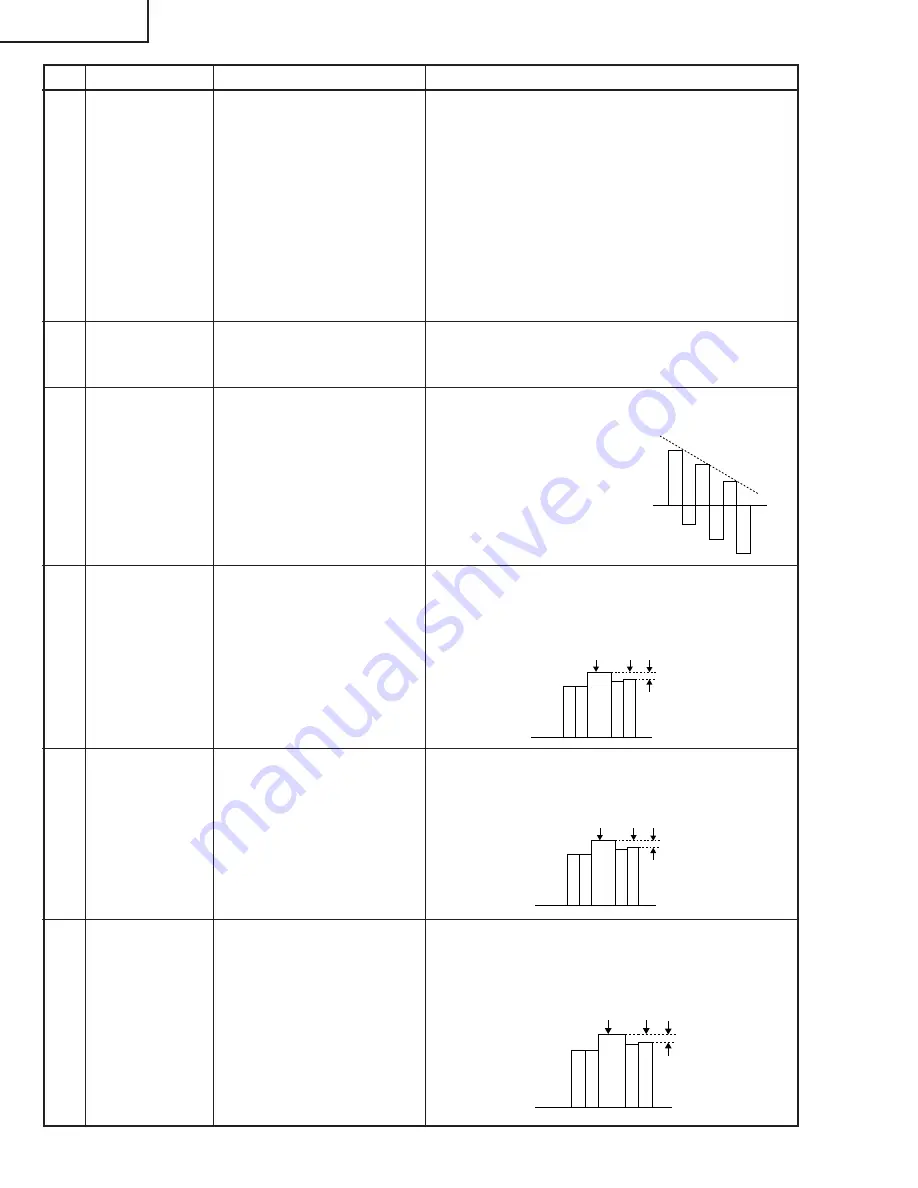
100% White Red
100% White Red
100% White Red
No.
Adjusting point
Adjusting conditions
Adjusting procedure
16
Video
brightness
adjustment
1. Feed the baseband (split
colour bar) signal. (The ON-
AIR signal is not accepted
because of its too much
noise.)
Group : VIDEO 2
Subject : VROS/VGOS/VBOS
2. Press the control switch or
the remote control’s mute
button (to set the gamma
correction to the process
setting).
»
Using the control switches or the remote controller
buttons, adjust the setting until the black signal
becomes bit-less.
17
Video AGC
1. Feed the split colour bar signal.
Group : VIDEO 1
Subject : AGC
»
Using the control switches or the remote controller
buttons, adjust the setting until the white signal
becomes bit-less.
18
Tint
1. Feed the split colour bar
signal.
Group : VIDEO 1
Subject : TINT
2. Connect the oscilloscope to
pin (4) of P801.
»
Using the control switches or the remote controller
buttons, adjust the data to have the -(B-Y) wave-
form downhill straight.
»
After adjusting, adjust the
value of TINT up 3 point.
19
NTSC colour
saturation level
1. Feed the split colour bar sig-
nal.
Group : VIDEO 1
Subject : N-COLOR
2. Connect the oscilloscope to
pin (1) of P801.
»
Using the control switches or the remote controller
buttons, adjust the difference between the 100%
white portion and the red portion to 0.00
±
0.05 Vp-p.
(same as 100% white)
20
PAL colour
saturation level
1. Feed the PAL colour bar sig-
nal.
Group : VIDEO 1
Subject : P-COLOR
2. Connect the oscilloscope to
pin (1) of P801.
»
Using the control switches or the remote controller
buttons, adjust the difference between the 100%
white portion and the red portion to 0.2
±
0.05 Vp-p.
21
SECAM colour
saturation level
1. Feed the SECAM colour bar
signal.
Group : VIDEO 1
Subject : S-COLOR
2. Connect the oscilloscope to
pin (1) of P801.
»
Using the control switches or the remote controller
buttons, adjust the data to have a level difference
of 0.2
±
0.05 Vp-p between the 100% white portion
and the red portion.
Summary of Contents for Notevision XG-C40XE
Page 92: ...93 92 XG C40XU XE 8 7 9 6 5 4 3 17 16 19 18 15 14 13 12 11 10 IS LAYOUT CHASSIS ANORDNUNG ...
Page 93: ...95 94 XG C40XU XE 8 7 9 6 5 4 3 17 16 19 18 15 14 13 12 11 10 DIAGRAM BLOCKSCHALTBILD ...
Page 104: ...115 114 XG C40XU XE 8 7 9 6 5 4 3 17 16 19 18 15 14 13 12 11 10 T UNIT 1 6 AUSGABEEINHEIT 1 6 ...
Page 105: ...117 116 XG C40XU XE 8 7 9 6 5 4 3 17 16 19 18 15 14 13 12 11 10 T UNIT 2 6 AUSGABEEINHEIT 2 6 ...
Page 106: ...119 118 XG C40XU XE 8 7 9 6 5 4 3 17 16 19 18 15 14 13 12 11 10 T UNIT 3 6 AUSGABEEINHEIT 3 6 ...
Page 108: ...123 122 XG C40XU XE 8 7 9 6 5 4 3 17 16 19 18 15 14 13 12 11 10 T UNIT 5 6 AUSGABEEINHEIT 5 6 ...
Page 109: ...125 124 XG C40XU XE 8 7 9 6 5 4 3 17 16 19 18 15 14 13 12 11 10 T UNIT 6 6 AUSGABEEINHEIT 6 6 ...
Page 110: ...127 126 XG C40XU XE 8 7 9 6 5 4 3 17 16 19 18 15 14 13 12 11 10 UNIT VIDEOEINHEIT ...
Page 112: ...131 130 XG C40XU XE 8 7 9 6 5 4 3 17 16 19 18 15 14 13 12 11 10 UNIT 1 9 PC I F EINHEIT 1 9 ...
Page 113: ...133 132 XG C40XU XE 8 7 9 6 5 4 3 17 16 19 18 15 14 13 12 11 10 UNIT 2 9 PC I F EINHEIT 2 9 ...
Page 114: ...135 134 XG C40XU XE 8 7 9 6 5 4 3 17 16 19 18 15 14 13 12 11 10 UNIT 3 9 PC I F EINHEIT 3 9 ...
Page 115: ...137 136 XG C40XU XE 8 7 9 6 5 4 3 17 16 19 18 15 14 13 12 11 10 UNIT 4 9 PC I F EINHEIT 4 9 ...
Page 116: ...139 138 XG C40XU XE 8 7 9 6 5 4 3 17 16 19 18 15 14 13 12 11 10 UNIT 5 9 PC I F EINHEIT 5 9 ...
Page 117: ...141 140 XG C40XU XE 8 7 9 6 5 4 3 17 16 19 18 15 14 13 12 11 10 UNIT 6 9 PC I F EINHEIT 6 9 ...
Page 118: ...143 142 XG C40XU XE 8 7 9 6 5 4 3 17 16 19 18 15 14 13 12 11 10 UNIT 7 9 PC I F EINHEIT 7 9 ...
Page 119: ...145 144 XG C40XU XE 8 7 9 6 5 4 3 17 16 19 18 15 14 13 12 11 10 UNIT 8 9 PC I F EINHEIT 8 9 ...
Page 120: ...147 146 XG C40XU XE 8 7 9 6 5 4 3 17 16 19 18 15 14 13 12 11 10 UNIT 9 9 PC I F EINHEIT 9 9 ...


