background image

Ver. 1.0UJ Aug 25, 2008 


- 4 -                                                                    Installation Manual for PV modules 


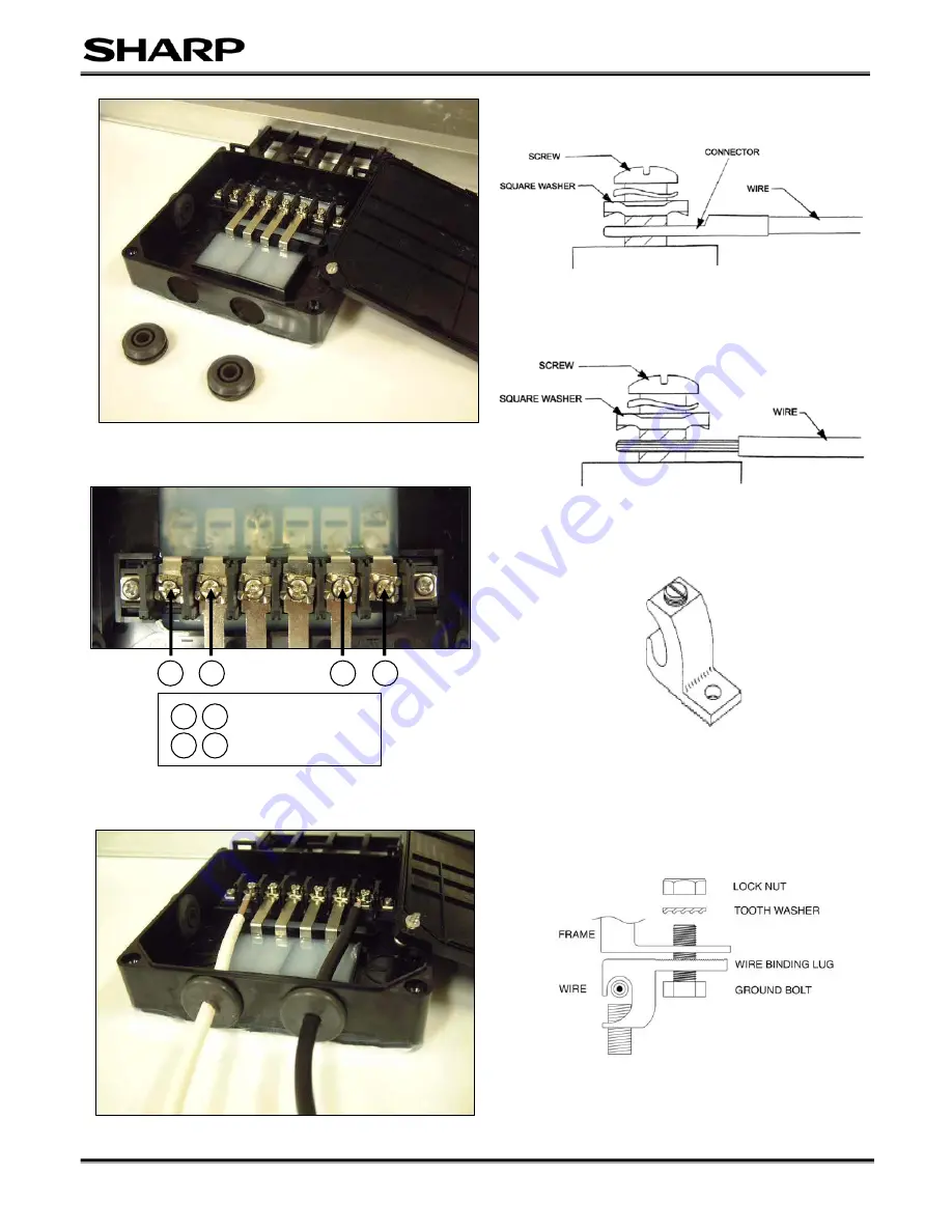
Remove the appropriate grommets. (Push them from inside of the box)

4

: Negative Terminal 

: Positive Terminal


Figure 3 

Figure 4 

Figure 5 

Figure 6 

Figure 7 

Figure 8 

Lay in Ground Lug 

Figure 9 

Summary of Contents for ND-123UJF

Page 1: ... In the case of a brushless motor the lock function may become active and the motor may be damaged 2 In the case of a brush type motor the coil may be damaged GENERAL SAFETY 1 Consult local codes and applicable laws concerning required permits and regulations concerning installation and inspection requirements 2 Install PV modules and ground frames and other metal components in accordance with app...

Page 2: ...The glass surface and the frame may be hot There is a risk of burns and electric shock 4 Do not work in rain snow or windy conditions 5 Use insulated tools 6 Do not use wet tools 7 When installing PV modules do not drop any objects e g PV modules or tools 8 Make sure flammable gases are not generated or present near the installation site 9 Terminate module to module wires in the junction box fully...

Page 3: ...observe correct cable connection polarity as shown Figures 1 and 4 If not connected correctly the bypass diodes could be destroyed This will void your warranty Open the cover of the junction box by loosening the two cover screws as shown in Figure 2 Figure 3 shows the inside of the junction box Typical terminal cabling is AWG 14 but will be dependent upon system design as guided by the National El...

Page 4: ...tallation Manual for PV modules Remove the appropriate grommets Push them from inside of the box 1 2 3 4 Negative Terminal 1 2 3 4 Positive Terminal Figure 3 Figure 4 Figure 5 Figure 6 Figure 7 Figure 8 Lay in Ground Lug Figure 9 ...

Page 5: ...elsewhere in this manual ND 123UJF ND 130UJF Maximum Power Pmax 123 0 W 130 0 W Open Circuit Voltage Voc 21 78 V 21 90 V Short Circuit Current Isc 7 99 A 8 20 A Voltage at maximum power Vpmax 17 21 V 17 40 V Current at maximum power Ipmax 7 15 A 7 50 A Maximum System Voltage 600 V 600 V Minimum Blocking diode 15 A 15 A Maximum Series Fuse 15 A 15 A Under normal conditions a PV module may produce m...

Page 6: ...s limited warranty the purchaser should follow the steps set forth below and provide proof of purchase to the servicer The limited warranty described herein is in addition to whatever implied warranties may be granted to purchasers by law ALL IMPLIED WARRANTIES INCLUDING THE WARRANTIES OF MERCHANTABILITY AND FITNESS FOR USE ARE LIMITED TO THE PERIOD S FROM THE DATE OF THE PURCHASE SET FORTH BELOW ...

Page 7: ...p for the Product or service which gave rise to the claim under the Limited Warranty The repair replacement of the Product or the supply of additional Product does not cause the beginning of new warranty terms nor shall the original warranty terms of this Limited Warranty be extended Any replaced product shall become Sharp s property Where to Obtain Service Warranty service is available at a Sharp...

Reviews: