Sharp MX 3501N - Color Laser - Copier Installation Manual Download Page 49

MX3500N  MX-RBX1, MX-FNX2  7 – 7

3)

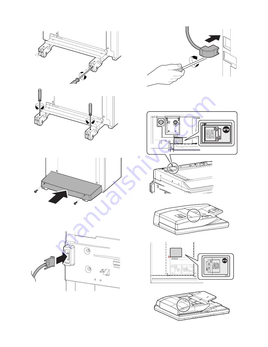
Loosen four fixing screws of the adjustment section, and turn
the height adjustment screws on the front/rear sides to adjust
so that the clearances are even.

4)

When the clearances are even, tighten the fixing screw of the
adjustment section, and install the foot cover.

F. Connector connection

1)

Connect the finisher connector with the connector of the inter-
face pass unit, and tighten the screw.

2)

Connect the finisher connector with the connector of the main
unit, and tighten the screw.

G. Staple position label attachment

1)

Attach the label to the position indicated in the figure.

[For scanner] (package part No. 8)

[For RSPF/DSPF] (package part No. 9)

Label attachment
reference

* Corner of the

"upper cabinet rear"

Corner R end fitting

Corner R end fitting

Cleaning of the document scan section

DSPF

RSPF

CAUTION

When streaks appear on copy or scan
images, open the automatic document
feed unit and clean the document scan
section with the glass cleaner (accessory).

Document scan section

Summary of Contents for MX 3501N - Color Laser - Copier

Page 1: ...2x500 sheet paper drawer 2 1 3 MX TRX2 Exit tray unit 3 1 4 MX LCX1 Large capacity tray 4 1 5 MX FNX1 Finisher 5 1 6 MX PNX1A B C D Punch module For Inner Finisher 6 1 7 MX RBX1 MX FNX2 Paper pass unit Saddle stitch finisher 7 1 8 AR PN1A B C D Punch module For Saddle stitch finisher 8 1 9 MX FRX2 MX FRX2U Data security kit 9 1 10 MX PKX1 PS3 expansion kit 10 1 11 AR PF1 Barcode font kit 11 1 12 M...

Page 2: ...urity ROM FAX memory 8MB packed together CD CD CD CD CD CD CD MX USX1 USX5 19 Sharpdesk 10 license kit 20 Sharpdesk 50 license kit MX US10 US50 21 Sharpdesk 100 license kit MX USA0 23 Facsimile expansion kit MX FXX1 ROM 13 Commercial version 1 Stand 1x500 sheet paper drawer MX DEX3 2 Stand 2x500 sheet paper drawer MX DEX4 3 Large capacity tray MX LCX1 7 Finisher MX FNX1 5 Paper pass unit MX RBX1 1...

Page 3: ...RX2 OPT 5 Paper pass unit MX RBX1 OPT 6 Saddle stitch finisher MX FNX2 OPT 7 Finisher MX FNX1 OPT Inner finisher 8 Punch module For inner finisher MX PNX1 A B C D OPT 9 Punch module For saddle stitch finisher AR PN1 A B C D OPT Common in current models 10 Staple cartridge For inner finisher MX SCX1 OPT Approx 5000 x 3 11 Staple cartridge For saddle stitch finisher AR SC2 OPT Approx 5000 x 3 Electr...

Page 4: ...ed voltage 10 If the voltage is outside the specified range use thicker lead wires to reduce impedance An electrical work is required Use of a step up transformer is also available In this case the capacity must be great enough for the max power consumption of the machine 3 Power frequency waveform The frequency must be within the range of the specified frequency 2 If power waveform is deformed a ...

Page 5: ...Transit and delivery A Implements facility and manpower It is recommendable to use a forklift for bringing in the machine for safety If no forklift is available man power of four persons is required The machine is considerably heavy and requires safety precautions for delivery and installation Transit of the machine must be made in packed condition to the installing place Since the hard disk drive...

Page 6: ...e tier paper feed desk MX DEX3 or two tier paper feed desk MX DEX4 then unpack the main unit and securely place the main unit on the MX DEX3 or MX DEX4 see 2 2 before installing the main unit A Lock release 1 Tray rotation plate lock release 1 Pull out the tray and remove the rotation plate fixing material and the tray note label 2 Attach the removed fixing material to the position shown in the fi...

Page 7: ...sing 1 Open the front cover 2 Check that the lock is released as shown in A Loosen the blue screw and open the drum positioning unit When the lock is not released use a screwdriver to turn the screw B counterclockwise so that it is fit as A 3 Open the DV lock lever and release the fixing screw 1 posi tion for each color 4 Pinch the knob and remove the development unit 1 2 NOTE If the machine is le...

Page 8: ... cleaner unit Since titanium hydroxide is of fine powder it may disperse when removing from the bag To prevent against dispersion remove it from the bag at a lower position Pushing the bag lightly against the belt provides sufficient application of titanium hydroxide Lift the bag from the appli cation surface by 5 mm or less Apply titanium hydroxide before installing the cleaner unit 2 Install the...

Page 9: ...ircuits of the belt Repeat half around application and half around rotation each 4 times Apply titanium hydroxide not to produce bias Application amount 7 Face the primary transfer UN upward Face the primary transfer UN UPward from the cleaner UN side Take care that powders will not fly apart 8 Mount the primary transfer UN on the machine and execute simulation 25 1 3 minute belt idling once 9 Che...

Page 10: ...r in the developer unit When replacing developer use an extreme care not to drop developer on the drive section marked with 4 Install the DV cover in the arrow direction A When installing the DV cover be sure to engage the pawl with the boss 5 Fix the DV cover with the two screws 6 Shake the developer unit horizontally a few times When supplying developer do not tilt the developing unit B A B A A ...

Page 11: ...1 F Set the control level for the reference toner density 1 Connect the earth cord and insert the power plug into the power outlet 2 Turn ON the power switch in the front cabinet 3 Turn ON the power switch on the operation panel 4 With the front cabinet open enter the data for Simulation 25 2 1 2 ON ON ON 0 SIMULATION NO 25 02 TEST AUTOMATIC DEVELOPER ADJUSTMENT EXECUTE AT DEVE ADJ_L_K 128 AT DEVE...

Page 12: ...nt to approximately 15 0K A4 LT 5 1 Shake the toner cartridge package part No 1 horizontally several times 2 Remove the heat seal 3 Open the front cover and insert each toner cartridge Be sure to install the color cartridges to their proper posi tions Avoid installation to a different color position Do not forcibly insert the toner cartridge Keep holding the cartridge and completely insert it When...

Page 13: ...imes to clean the LSU dust proof glass 5 Replace the LSU claning bar to the front cover and attach the waste toner bottle unit 6 Close the front cabinet I Installation of the operation manual pocket 1 Install the Operation Manual storage package part No 3 cover to the left side of the machine First insert the pawl on the lower side of the Operation Manual pocket Then lift the pawl on the upper sid...

Page 14: ...gs Admin Password Default Settings Total Count Address Control Exit List Print User Fax Data Receive Forward USB Device Check Paper Tray Settings Printer Condition Settings Document Filing Control System Settings Paper Tray Settings OK Tray Settings Paper Type Registration Auto Tray Switching System Settings Paper Tray Settings Type Size Tray 1 Fixed Paper Side Disable Duplex Disable Staple Disabl...

Page 15: ...a scale on the document table 2 Enter the simulation 50 1 mode 3 Perform the image lead edge reference position adjustment 4 If the adjustment is required adjust image lead edge reference position by changing the setting value 5 Perform the image loss adjustment Copy image position image loss adjustment RSPF mode Refer to the MX RPX1 SM 4 Copy color balance adjustment Auto adjustment a Note before...

Page 16: ... EXECUTE key The copy color balance adjustment is automatically executed and prints the color balance check patch image Wait until the operation panel shown in the next procedure is displayed 4 0 SIMULATION NO 46 24 TEST ENGINE HALFTONE AUTO ADJUSTMENT PLEASE SELECT THE MODE FACTORY OR SERVICE AND PLACE THE PRINTED TEST PATCH ON DOCUMENT GLASS THEN PRESS EXECUTE 㪁LIGHT AREA AT LEFT SIDE ON DOCUMEN...

Page 17: ...nts must be made again If the data are kept the setup values and the adjustment values can be entered without adjustments shortening the servicing time O Necessary works before moving the machine 1 If the following options are installed remove all of them from the machine Saddle stitch finisher Large capacity tray 2 Remove the following consumable parts from the machine Paper Toner cartridge Devel...

Page 18: ...C Check the packed items 1 Check that all the items are included in the package 2 Installation Note before installation Before starting installation check to insure that the data lamp on the operation panel does not light up or blink A Turn off the power of the main unit 1 Turn OFF the power switch on the operation panel 2 Open the front cabinet Turn OFF the power switch in the front cabinet of th...

Page 19: ...covers of the both sides of the main unit 2 Put the main unit on the desk unit Use man power of four persons or more to lift the main unit Place the main unit on the desk unit slowly by fitting the external lines Check to insure that the positioning pin on the top of the desk unit is securely engaged in the positioning groove of the main unit 3 Remove the No 2 paper feed tray 4 Pull out the No 3 p...

Page 20: ...t and left of the main unit front side and fix them with the fixing screws package part No 2 6 Replace the No 3 and No 2 trays to the original positions 7 Lift the connection plates and fix them with the fixing screws 8 Install the connection plate covers 1 2 2 1 2 1 ...

Page 21: ...was pulled out E Connector connection 1 Remove the screw from the back of the main unit Remove the connector cover 2 Connect the connector 3 Split the removed connector cover along the perforated line 4 Install the connector cover and fix it with a screw NOTE Before turning on the power check to insure that the fixing material of the tray is disengaged If the power is turned on without disengaging...

Page 22: ...causes the main scan print position to shift by 0 1 mm toward the front 5 After entering the adjustment value press the EXECUTE key on the touch panel to start printing and save the setting 6 Check that the adjustment pattern image is printed in the cor rect position Measure the dimensions of the void areas on the front and rear frame sides of the adjustment pattern image and make sure that the fo...

Page 23: ...oes not light up or blink A Turn off the power of the main unit 1 Turn OFF the power switch on the operation panel 2 Open the front cabinet Turn OFF the power switch in the front cabinet of the main unit 3 Remove the earth cord and disconnect the power plug of the main unit from the power outlet B Installation of the exit roller unit 1 Open the right door 2 Remove the screw and remove the connecto...

Page 24: ...it with the screw 6 Install the exit tray unit A and the full detection actuator B package part No 2 Be careful of the installing direction of the full detection actu ator C Turn on the power of the main unit 1 Connect the earth cord and insert the power plug of the main unit into the power outlet 2 Open the front cabinet Turn ON the power switch in the front cabinet of the main unit 3 Turn ON the...

Page 25: ...starting installation check to insure that the data lamp on the operation panel does not light up or blink A Turn off the power of the main unit 1 Turn OFF the power switch on the operation panel NOTE Before turning on the power check to insure that the fixing screw of the tray is removed If the power is turned on without removing the fixing screw a trouble may be resulted 1 3 4 2 5 No Names of bu...

Page 26: ...nit 1 Install the mounting plate upper package part No 1 to the right side of the main unit with the fixing screw A package part No 3 When installing put the rubber section of the mounting plate upper on the lower side 2 Remove the right door cover from the machine 3 Disengage the pawl and remove the right adjuster 4 Remove the screw cap and remove the screw 5 Remove the cover 6 Temporarily fix th...

Page 27: ... to the main unit 2 Check to insure that the height adjustment check rib of the large capacity tray unit and the axis line of the mounting plate upper mounted to the main unit are in the same line 3 If the height adjustment is not required insert the large capac ity tray unit further more If the height adjustment is required perform the adjustment procedures from 4 4 Loosen the adjustment screw on...

Page 28: ... line of the mounting plate upper and insert the large capacity tray unit 7 Tighten the loosened screw D Connector connection 1 Remove the screw and remove the connector cover 2 Connect the connector and tighten the screw E Paper size switch 1 Paper size switch from A4 to LT Since the factory setting of the paper size is A4 if paper size switch is required perform the following procedures 1 Slowly...

Page 29: ...ide 3 Set the mark position of the auxiliary guide and the cas sette R to the size from A4 to LT and fix with the fixing screw flat screw At that time set the mark position of the auxiliary guide and the cassette R to the same scale of the mark position of the side plate R and the size guide adjustment plate con firmed in procedure 1 If the scale of the size guide adjust ment plate is at the cente...

Page 30: ...wing procedures 1 Slowly pull out the tray until it stops 2 Loosen the stopper fixing screw 1 pc on the right lower side of the tray so that the stopper does not function 3 Pull out the tray again until it stops a Side plate size switch 1 Remove four fixing screws blue screws which are fixing the upper and the lower sections of the side plate F and the side plate R 2 Adjust the mark position of th...

Page 31: ...er section with the fixing screw blue screw which was removed previously NOTE When the rear edge shaft is switched to B5 check to confirm that the side plates F R are already set to B5 If the side plates F R are not set to B5 the rear edge shaft cannot be switched to B5 3 Slightly push the tray restore the stopper to the original posi tion and fix the fixing screw At that time check to insure that...

Page 32: ...CUTE key on the touch panel to start printing and save the setting 6 Check that the adjustment pattern image is printed in the cor rect position Measure the dimensions of the void areas on the front and rear frame sides of the adjustment pattern image and make sure that the following conditions are met No adjustment is needed if A B 0 3 0 mm If the above condition is not met do the following 7 Cha...

Page 33: ...nal position Then make a copy to check to insure that there is no more shift Repeat the procedures until there is no shift b When the shift is in the rear side To adjust the print line in the direction B from the paper center as shown in the figure 1 Loosen two fixing screws red screws of the front rear size guide adjustment plate and move the size guide adjustment plate in the direction B F side ...

Page 34: ...nd protection material C Check the packed items 1 Check that all the items are included in the package 10 11 12 1 4 8 9 2 5 6 7 3 No Packed part names Quantity 1 Finisher fixing plate 1 2 Front slide rail 1 3 Dummy punch unit 1 4 Front open close cover 1 5 Punch cover 1 6 Left front cover 1 7 Finisher slide stopper 8 8 Fixing screw 1 9 Resin clip 1 10 Coin screw 1 11 Staple position label For scan...

Page 35: ...inet of the main unit 3 Remove the earth cord and disconnect the power plug of the main unit from the power outlet B Removal of the paper holding arm unit 1 Push up the section A to disengage the pawl and remove the paper holding arm and the paper holding arm holder together as a unit Be careful to remove both of the paper holding arm which is easily removed alone and the paper holding arm holder ...

Page 36: ... 7 Fix the right cover plate with the fixing screw package part No 8 Fix the side plate of the paper exit shifter with the fixing guide 8 Install the front slide rail A package part No 2 with the three fixing screws package part No 8 and install the left front cover B package part No 6 with one fixing screw package part No 8 9 Fix the dummy punch unit package part No 3 with the fixing screw packag...

Page 37: ...ge part No 5 together with the band metal fixture with the fixing screw package part No 8 15 Install the front cabinet upper with two screws D Connector connection 1 Remove the protection material and fixing tape 2 Remove the screw and remove the connector cover 3 Connect the finisher connector with the main unit connector and tighten with a screw E Staple position label attachment 1 Attach the la...

Page 38: ... into the power outlet 2 Open the front cabinet Turn ON the power switch in the front cabinet of the main unit 3 Turn ON the power switch on the operation panel DSPF RSPF CAUTION When streaks appear on copy or scan images open the automatic document feed unit and clean the document scan section with the glass cleaner accessory Document scan section ON ON ON ...

Page 39: ...all the punch unit Note before installation Before starting installation check to insure that the data lamp on the operation panel does not light up or blink Do not install the punch unit first because doing so would cause interference between the inner finisher slide rail and the punch unit drawer connector possibly resulting in failure when you attempt to install the inner finisher A Turn off th...

Page 40: ... of the main unit from the power outlet B Installation of the punch unit 1 Open the front cabinet 2 Open the front lid and slide the inner finisher 3 Remove the coin screw and remove the finisher slide stopper 4 Slide the inner finisher further more 5 Remove two screws and remove the front cabinet upper 6 Remove the screw and remove the band and the punch cover OFF 2 1 ...

Page 41: ...oning with the dove A and fix the punch unit with the screw which was fixing the dummy punch unit 10 Cut the lid of the punch cover with nippers 11 Remove the dust box 12 Fix the punch cover and the band together with one screw 13 Insert the dust box 14 Install the front cabinet upper part using the two screws removed in step 5 15 Insert the finisher slide stopper between the slide rail and the ac...

Page 42: ...e power outlet 2 Open the front cabinet Turn ON the power switch in the front cabinet of the main unit 3 Turn ON the power switch on the operation panel 2 1 Label attachment reference Corner of the upper cabinet rear Corner R end fitting Corner R end fitting No clearance Second label First label DSPF RSPF R2 5 connection line Cleaning of the document scan section When streaks appear on copy or sca...

Page 43: ...efore starting installation check to insure that the data lamp on the operation panel does not light up or blink A Turn off the power of the main unit 1 Turn OFF the power switch on the operation panel 2 Open the front cabinet Turn OFF the power switch in the front cabinet of the main unit 1 2 3 4 5 6 7 8 No Packed part names Quantity 1 Right cover plate 1 2 Interface left cabinet 1 3 Reverse tray...

Page 44: ...he front cabinet Remove the screws and remove the front cabinet upper 2 Disengage the pawls and remove the paper exit tray cover 3 Remove the screws and remove the paper exit tray 4 Remove the paper exit full detection actuator A and install the reverse detection actuator B package part No 7 Be careful of the installing direction of the reverse detection actuator 5 Engage the projection of the mai...

Page 45: ...ace left cabinet and the top surface of the right cover plate When inserting the reverse tray check to insure that the switch guide of the reverse tray is up 8 Fix the reverse tray with the ornamental screw package part No 6 9 Install the front cabinet upper and fix with the screws 10 Fix the stopper package part No 8 with the fixing screw B package part No 5 11 Insert the interface pass unit alon...

Page 46: ...X RBX1 be installed in advance Be sure to complete the installation of the option desk MX DEX1 DEX2 and junction unit MX RBX1 before installing the saddle finisher Make sure that the connection plate provided on the front side of the option desk is securely installed Make sure that the connection plate package part No 2 included in the package is securely installed A Replacement of the Operation M...

Page 47: ... package part No 5 2 Install the rail bracket to the frame with four fixing screws B package part No 6 C Staple unit installation 1 Open the front cover of the finisher and insert the staple unit package part No 3 2 As shown in the figure rotate the roller rotation knob so that the triangle mark is fit with the indication 3 Insert the staple cartridge package part No 4 into the staple section unti...

Page 48: ...r side Adjust the height adjustment screw so that the guide pin is fit with the connection hole in the finisher 2 Loosen the fixing screw of the adjustment section on the front side If the guide pin is inserted smoothly tighten the fixing screws of the adjustment section on the front rear sides 2 When the guide pin is fit with the connection hole in the finisher 1 Insert the finisher into the main...

Page 49: ...it and tighten the screw 2 Connect the finisher connector with the connector of the main unit and tighten the screw G Staple position label attachment 1 Attach the label to the position indicated in the figure For scanner package part No 8 For RSPF DSPF package part No 9 Label attachment reference Corner of the upper cabinet rear Corner R end fitting Corner R end fitting Cleaningofthedocumentscans...

Page 50: ...tch in the front cabinet of the main unit 3 Turn ON the power switch on the operation panel I Storage of the paper entry guide 1 When the punch unit is not installed store the paper entry guide package part No 7 to the position in the saddle finisher section as shown in the table below Pinch the paper guide with the plate A and then insert the boss B in the hole in the paper guide ON ON ON A B B 1...

Page 51: ... the operation panel does not light up or blink A Turn off the power of the main unit 1 Turn OFF the power switch on the operation panel 2 Open the front cabinet Turn OFF the power switch in the front cabinet of the main unit 3 Remove the earth cord and disconnect the power plug of the main unit from the power outlet 4 Disconnect the connector between the main unit and the sad dle finisher No Pack...

Page 52: ...rear cabinet upper in the arrow direction C Remove the interface harnesses 2 pcs from the outlet port of the rear cabinet upper 5 Remove the screws Open the top door and remove the right cabinet upper and the right cabinet middle 6 Remove the pawls 2 positions of the upper cover and sepa rate it into the upper and the lower sections Reuse the upper section C Replacement of the paper entry paper gu...

Page 53: ...driver 6 Remove the paper entry paper guide 7 Install the paper entry paper guide exclusively used for the MX FNX2 packed with the saddle finisher 8 Fix the incoming paper guide using the screws removed in step 2 9 Replace the dust box to the original position 10 Install the punch unit and fix it with the screws Connect the connector 1 2 Fixing screw Punch unit Fixing screw Fixing screw M4 x 6 wit...

Page 54: ...harnesses 2 pcs through the rear cabinet upper While opening the upper door install the rear cabinet upper and fix it with screws 14 Install the front cabinet upper and fix it with the screws Install the front cabinet upper so that the projection of the latch arm is in the hole in the lock release lever 15 Install the knob and close the front cover 16 Install the saddle finisher to the main unit H...

Page 55: ...sert the power plug of the main unit into the power outlet 3 Open the front cabinet Turn ON the power switch in the front cabinet of the main unit Label attachment reference Corner of the upper cabinet rear Corner R end fitting Corner R end fitting No clearance Second label First label DSPF RSPF R2 5 connection line Edge line R 2 5 Cleaning of the document scan section When streaks appear on copy ...

Page 56: ...hat the LED1 on the finisher control PWB flashes at a certain interval Set the DIP SW 2 and 5 to ON to execute the mechanism ini tializing of the finisher 3 After completion of the mechanical initializing press DSW1 to perform the automatic adjustment of the dust full sensor After completion of the adjustment the LED2 lights up 4 Set all the DIP switches to OFF and check to confirm that the LED2 t...

Page 57: ...on panel has gone out open the front cabinet and turn the main power switch to the OFF posi tion 3 Remove the power plug of the main unit from the outlet B Pull out the control PWB If cables are connected to the control PWB unit remove all cables 1 Push the location indicated in the illustration to unlock and remove the ozone filter cover from the right rear cabinet 2 Remove the screw from the rig...

Page 58: ...g the DOCC PWB F Attach the DOCC PWB 1 Connect the connector of the DOCC PWB to the 30 pin con nector of the Mother PWB 2 Use the four screws that have been removed in step E 2 and 5 to secure the DOCC PWB 3 Connect the 12 pin and 15 pin connectors of the main unit to the connectors on the DOCC PWB 4 Ensure that pins 1 and 2 of the DIP switch on the DOCC PWB are OFF G Attach the rear cabinet 1 Han...

Page 59: ...ouch Enter key 2 After completing product key entry turn off the power switch on the operation panel of the main unit and then turn off the main power switch Then turn on the main power switch and then turn on the power switch on the operation panel of the main unit again After the power switches are turned on message Please wait may appear and encryption and deletion of data may take several minu...

Page 60: ... t use the back print paper c Set on the document table the each paper that printed by procedure b and copy it d After copy operating Detected the document control pat tern Job is aborted is displayed on the touch panel If the message displayed and no print is made the operation check is completed If the result executed by each color Y Yellow C Cyan Bk Black displays Detected the document control ...

Page 61: ...he product key by the key operation of the copier machine a Touch PRODUCT KEY INPUT b Enter the product key with the 10 key and touch OK key 2 After completion of the product key entry turn OFF the power switch and the main power switch and turn them ON B PS3 check 1 Print the test page in PS3 fonts by the key operation of the operation panel Select the PS font list by the procedures described in ...

Page 62: ...he PWB is installed The connector position is indicated by the silk print on the PWB 5 Install the MFP PWB shield plate upper and connect the con nector 6 Install the rear cabinet 7 Insert the power plug of the copier into the power outlet Turn ON the power switch and perform the following procedures B PCL expansion font list check 1 PCL expansion font list check Select the PCL expansion font list...

Page 63: ...im Regular 9 Code39SmallLow Regular 10 Code39SmallMedium Regular 11 Code39Wide Regular 12 Codabar Regular 13 Interleaved2of5 Regular 14 Interleaved2of5 Thin Regular 15 OCR A 16 OCR B 17 OCR B C39 Regular 18 Upc Half 19 Upc Half Bars 20 Upc HalfMusic 21 Upc HalfNarrow 22 Upc HalfThin 23 Upc Tall Regular 24 Upc TallBarsThin regular 25 Upc TallMusicThin Regular 26 Upc TallNarrow Regular 27 Upc TallTh...

Page 64: ... the Application Integration Module function enter the product key by the key operation of the operation panel a Touch Product Key b Enter the product key with the 10 key and touch Enter key 2 After completion of the product key entry turn OFF the power switch and the main power switch of the machine and turn them ON again For the models with the main power switch only turn OFF ON the main power s...

Page 65: ...ain power switch to the OFF opsi tion 3 Remove the power plug of the main unit from the outlet B Attach the fax box unit to the rear part of the main unit 1 Remove the two screws from the rear cabinet of the main unit 2 Attach the supplied step screw to one of the two positions from which the screws are removed 3 Insert the step screw into the mounting hole of the fax box unit 4 Use a screw that h...

Page 66: ...ace cable into the recessed portion of the sheet metal on the control PWB unit 3 Attach the snap band to the sheet metal of the control PWB unit F Attach the control PWB and the right rear cabinet 1 Push the control PWB unit into the main unit and secure it with the two screws 2 Cut out the cut out portion of the right rear cabinet 3 Fit the interface cable into the opening that has been cut 4 Att...

Page 67: ...Use the numeric keys to enter 66 in the main code entry screen shown below and press the START key 3 Use the numeric keys to enter 02 in the sub code entry screen shown below and press the START key 4 Use numeric keys 0 and 1 to enter the desired 8 digit coun try code After entry press SET EXECUTE and YES in this order Country code list screen Press the DEST CODE button on the initial screen to mo...

Page 68: ...nel After YES on the panel lights up press it 5 The screen shown below is displayed and memory clear oper ation is executed 6 After several minutes memory clear operation is completed and the YES button goes out Press the CA key to exit from the simulation mode Then the main unit is automatically rebooted K Connect the line cable to the fax box unit Connect the line cable of the line side to the m...

Page 69: ...ch and the main power switch After completion of 1 and 2 the Internet Fax send function from the main unit becomes enable To enable the Internet Fax send with the PC FAX driver the following steps 3 and 4 are required 3 Use the CD ROM packed together with the machine to install the PC FAX driver For installing procedures refer to the software setup guide 4 Update the PC FAX driver with the CD ROM ...

Page 70: ...bout 220 C which is about 40 C higher than that of conventional lead solder and its soldering capacity is inferior to conventional one it is apt to keep the soldering iron in contact with the PWB for longer time This may cause land separation or may exceed the heat resistive temperature of components Use enough care to separate the soldering iron from the PWB when completion of soldering is confir...

Page 71: ...sfara vid felaktigt batteribyte Använd samma batterityp eller en ekvivalent typ som rekommenderas av apparattillverkaren Kassera använt batteri enligt fabrikantens instruktion German Achtung Explosionsgefahr bei Verwendung inkorrekter Batterien Als Ersatzbatterien dürfen nur Batterien vom gleichen Typ oder vom Hersteller empfohlene Batterien verwendet werden Entsorgung der gebrauchten Batterien nu...

Page 72: ... 2000 Windows XP Windows 2000 Server Windows Server 2003 and Internet Explorer are trademarks or copyrights of Microsoft Corporation in the U S A and other countries IBM and PC AT are trademarks of International Business Machines Corporation Acrobat Reader Copyright 1987 2002 Adobe Systems Incorporated All rights reserved Adobe the Adobe logo Acrobat and the Acrobat logo are trademarks of Adobe Sy...

Reviews: