background image

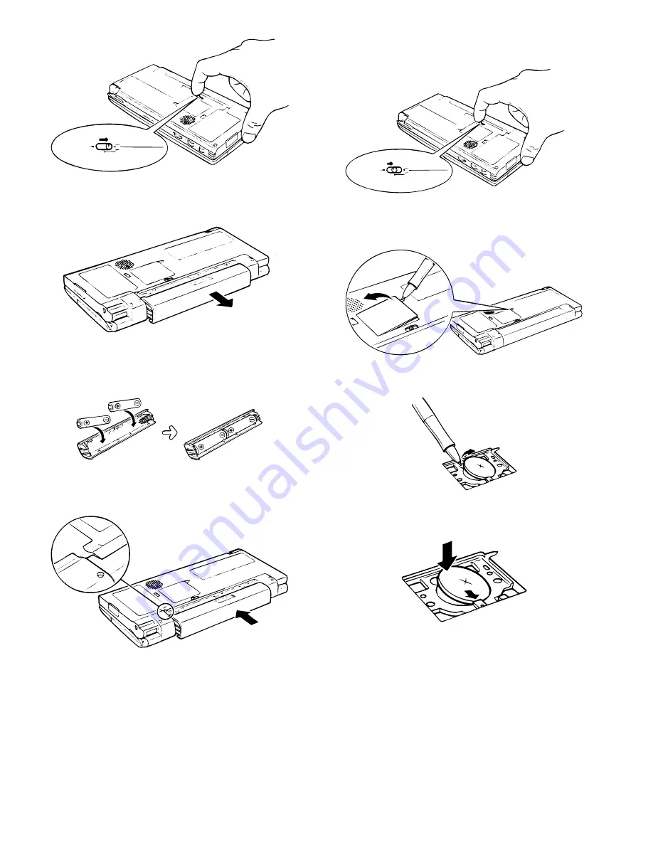
2. Slide the battery replacement switch to the REPLACE MAIN BAT-

TERIES position.

3. Pull out the battery holder and remove the old batteries. Discard

them properly.

4. Insert two new AA alkaline batteries into the battery holder, noting

the directions indicated by the plus (+) and minus (–) signs inside
the holder.

5. Reattach the battery holder to the unit, noting the position of the

projecting part on the battery holder.

6. Slide the battery replacement switch back to the NORMAL OP-

ERATION position.

If this proves difficult, check to make sure the main battery holder
is completely inserted.

7. After battery replacement, turn on the unit and make sure no

warning message appears.

Replacing the backup battery

1. Turn off the unit.

2. Slide the battery replacement switch to the REPLACE BACKUP

BATTERY position.

3. Use a ballpoint pen to open the backup battery cover. Do not use

the stylus.

4. Remove the old backup battery with a ballpoint pen.

5. Insert a new CR-2032 lithium battery with the plus (+) sign facing

up.

6. Put the backup battery cover back in place and slide the battery

replacement switch to the NORMAL OPERATION position.

7. After battery replacement, turn on the unit and make sure no

warning message appears.

NORMAL OPERATION

REPLACE MAIN BATTRIES

REPLACE BACKUP BATTERY

NORMAL OPERATION

REPLACE MAIN BATTRIES

REPLACE BACKUP BATTERY

– 36 –

Summary of Contents for Mobilon HC-4000

Page 1: ...5 DIAGNOSTICS AND CHECK ITEMS CHAPTER 6 CIRCUIT DIAGRAM PARTS LAYOUT PARTS GUIDE CONTENTS SHARP CORPORATION This document has been published to be used for after sales service only The contents are subject to change without notice Parts marked with is important for maintaining the safety of the set Be sure to replace these parts with specified ones for maintaining the safety and performance of the...

Page 2: ...R CONSUMPTION 1 8 W AUTO POWER OFF TIME 15 minutes MEMORY PROTECT Yes DIMENSIONS Open 186 W 187 D 14 1 H mm Closed 186 W 93 5 D 26 4 H mm Weight Approx 410 g including batteries Interfaces RS 232C RJ 11 Infrared port IrDA compliant IR send distance 50 cm 20 inch IR distance may change depending on the system used PC Card slot 1 Type II Internal Fax Modem Transmission speed Data modem 33 6 kbps Fax...

Page 3: ...communication 1 PC Card eject switch Slide to eject the inserted PC Card 2 Battery replacement switch For replacing main batteries as well as the backup battery 3 Main battery holder Holds two AA alkaline batteries or can be replaced with the op tional NiMH Rechargeable Battery Pack 4 Infrared port For wireless communication with other handheld PCs and infra red capable notebook and desktop PCs an...

Page 4: ... body HPC Explored Power PIMM Data conversion software from Zaurus Wizard AC adapter Serial port Battery pack Option cradle kit attached Spare battery charging box 1 IrDA system is supported Speed Max 115Kbps ASK system is not supported For wizard data import is allowed through PC 2 Fax MODEM is built in the models for North America only For the other areas use commercially available GSM adapter c...

Page 5: ...When the setting circuit is on Power to VRAM is supplied When the voltage between check pad VRAM and GND is 2 3V or above the setting circuit is on Note In the ZR 5700 5800 never make the following settings be fore shipment which will fasten backup battery exhaustion B and S keys B and C keys 2 Resetting the HC 4000 4100 If the unit stops responding while you are using it you can reset the unit Ma...

Page 6: ...mpletely inserted 7 After battery replacement turn on the unit and make sure no warning message appears Replacing the backup battery 1 Turn off the unit 2 Slide the battery replacement switch to the REPLACE BACKUP BATTERY position 3 Use a ballpoint pen to open the backup battery cover Do not use the stylus 4 Remove the old backup battery with a ballpoint pen 5 Insert a new CR 2032 lithium battery ...

Page 7: ...Panasonic type CR2032 only Use of another battery may present a risk of fire of explosion See operation manual for safety instructions Batteries may explode if mistreated Do not recharge except the optional NiMH Rechargeable Battery Pack disassemble or dis pose of in fire Connecting the unit to your PC You can connect the unit to your desktop PC to backup data syn chronize activities transfer file...

Page 8: ...ards Inserting a PC Card Insert the PC Card into the slot as far as it will go Make sure the PC Card is facing up If the card will not go in check the orientation Never force the card or it or the main unit may be damaged Removing a PC Card 1 Close all applications accessing or otherwise utilizing data on the inserted PC Card 2 Turn off the unit 3 Slide the eject switch to release the PC Card and ...

Page 9: ...ghlight the desired data 3 On your unit tap Receive from the File menu then select ZR Series 4 Set the sending unit to the sending mode In case of SHARP ZR Series unit press SEND key then start receiving the data Notes on field mapping when receiving data from ZR Se ries unit PC files are received as they are without any conversion For Con tacts data the following rules apply Contact1 data on the ...

Page 10: ...A 23E for the ZR 3000 3500X 1 unit Floppy Disk 1 2 Check the label RS 232C cross cable Since the hardware flow is required RTS and CTS must be connected RS 232C level convertor CE 137T ZR 3000 3500X ROM V1 0 or later FLASH EEPROM writing software for MS Windows 95 Ver F F mm dd yy Disk content setup Writing tool Z lite x Vxx 3 Data 1 Trademark Microsoft 2 Supplied by SHARP In the future it may be ...

Page 11: ...s after checking the other items 43 ERASE 1M FLASH 45 VERIFY 1M FLASH 47 UPDATE 1M FLASH 5 3 Copying patch data to products from the ZR 3500X master unit Tools 1 ZR 3500X master unit 2 Data transfer cable CE 315L Procedure Connect the master set and the slave set with the cable Slave side 1 Start the DIAG menu ON D RESET 2 Touch the menu key three times 3 Touch 43 ERASE 1M FLASH 4 Touch 47 UPDATE ...

Page 12: ...tors fit the main side and the memory side properly and connect If positioning is improper they may be broken Note 2 When removing the memory PWB remove it from section A If it is removed from the other section a stress is applied to the docking connectors 2 Module cover attachment screw tightening 1 Insert two pawls of ROM module cover into the lower cabinet pawl engagement positions to attach 2 ...

Page 13: ...ert the microphone body into the cabinet Be careful of the inserting direction 3 Treat the wire not to cover the upper side of recording indicator button and screw hole A 2 Speaker lead wire process 3 Key lower cabinet screw tightening 1 Tighten six screws A Tightening torque 1 6kgf cm 7 2 Tighten two screws B Tightening torque 0 6kgf cm 7 Microphone Indicator filter 1 2 1 Microphone cone side A K...

Page 14: ...ch the recording LED indicator re lease button 3 PWB unit screw tightening 2 positions 4 Battery terminal soldering conditions Cover lock knob Return spring Serial port cover 1 2 3 1 Record button Cover lock spring LED Indicator release button Batt term Batt term Copper foil tape 2 1 Note Fit teh return spring so that it s protruded portion faces PWB inner side Return spring Cabinet unit under the...

Page 15: ...y PWB unit removal 1 Remove two screws 1 and remove chassis B 2 2 Remove fourteen screws 3 and remove key PWB unit 4 Note for assembly 1 Key upper cabinet key PWB unit screw tightening screw 14pcs Copper foil tape PWB unit Attachment reference PWB external shape Battery terminal soldering pad external shape Soldering pad Attachment reference Copper foil tape Solder Hinge unit Copper foil tape PWB ...

Page 16: ...le 6 and pressure rubber 7 4 Remove tablet unit 8 5 Remove LCD unit 9 Note for assembly 1 Attachment of tablet spacer to the tablet Use the jig 2 Attachment of tablet unit to the LCD unit Tightening torque 0 4kgf cm Key upper cabinet Chassis B screw tightening screw x 2 pcs Chassis B 25 SHARP Badge Cusion B Cusion A Table spacer 2 3 4 5 6 7 8 9 1 1 Do not extend Reference Do not extend Reference T...

Page 17: ... 1 Keep the lead wire away from the LED holder rib shaded section in the figure If not the lead wire may be pinched between the display cabinet A external cabi net rib 2 Keep the lead wire away from the tablet pressing angle including a screw The space between the display cabinet A ceiling is insufficient Lead wire work dimensions UL style 1571 AWG 28 lead LCD unit Reference Do not extend Referenc...

Page 18: ... lead wire 6 Key bottom cabinet disassembly Rug terminal QLUGE1005CCZZ Note Do not put solder on this side Solder Key bottom cabinet IR Filter Sheet Battery exchange knob Spring Battery box lock knob IC Cord cover Speaker Spring 46 ...

Page 19: ...cabinet Speaker lead wire must be in this range Speaker 0 5mm Lock knob return spring attachment Lock knob return spring 6 Attachment of lock knob return spring to the battery box lock Knob screw tightening Tightening torque 0 6Kgf cm 9 Battery box lock knob Key lower cabinet 2 Insert the card cover return spring into the card cover Attach the card cover to the key lower cabinet Card cover return ...

Page 20: ...over the parts indicated with Jumper wire No 5 pin C372 side side IC352 No 5pin Jumper wire Modular jack lead must be cut processed Cushion Cushion Attach the cushion to the center of the coil 2 positions asshown with arrows Wire material U L Style 1571 ILUX electrical wire AWG28 1 5mm 5 0 mm 1 5mm 5 0 mm 85mm 5 0 mm 2PIN Jack Soldering conditions Soldering time 3sec or less Solder tip temperature...

Page 21: ... stored in a retrieval system or transmitted in any form or by any means electronic mechanical photocopying recording or otherwise without prior written permission of the publisher SHARP CORPORATION Information Systems Group Quality Reliability Control Center Yamatokoriyama Nara 639 11 Japan 1997 October Printed in Japan S ...

Reviews: