background image

18

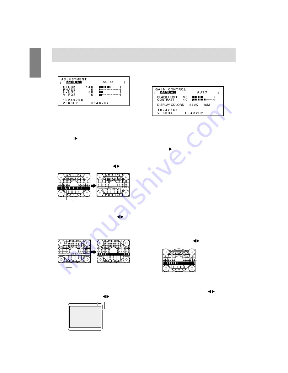
MENU 1: ADJUSTMENT

MANUAL: Individual menu options are manually

adjusted.

AUTO:

Every menu option is automatically
adjusted.

Notes:
-

Press the   button to select AUTO.

-

To choose a menu option:

SELECT button

-

To go to MENU 2:

MENU button

CLOCK

The figure below demonstrates how to adjust so that
vertical flicker noise is not emitted. (

 buttons)

PHASE

The figure below demonstrates how to adjust so that
horizontal flicker noise is not emitted. (

 buttons)

Note:
-

Adjustments to PHASE should be made only
after CLOCK has been correctly set.

H-POS (horizontal positioning) and V-POS
(vertical positioning)

To center the screen image within the boundaries of
the screen, adjust the left-right (H-POS) values and
the up-down (V-POS) values. (

 buttons)

MENU 2: GAIN CONTROL

BLACK LEVEL and CONTRAST are optimized
before shipment, but can be adjusted to suit.

MANUAL: Individual menu options are manually

adjusted.

AUTO:

Every menu option is automatically
adjusted using the Auto Gain Control*
function,

Notes:
-

Press the   button to select AUTO.

-

To choose a menu option:

SELECT button

-

To go to MENU 3:

MENU button

* Auto Gain Control function

-

The Auto Gain Control adjusts contrast and black
level based on the brightest color of the image
displayed. If you are not using the Adjustment
Pattern it is necessary to have an area of
5 mm x 5 mm of white displayed, and if not
adjustments may not be possible. (In such case,
[OUT OF ADJUST] will appear and setting values
remain unchanged.)

-

To perform the Auto Gain Control function, first go
to MENU 3 and set [WHITE BALANCE] to
something other than [USER]. If [USER] is set,
Auto Gain Control will be disabled.

BLACK LEVEL

Total screen brightness can be adjusted while
watching the color pattern. (

 buttons)

CONTRAST

While watching the color pattern, adjustments can be
made so that all graduations appear. (

 buttons)

DISPLAY COLORS

Maximum display colors can be set.
260K (260,000) and 16M (16.19 million)

Adjustment
Pattern

Screen frame

Color pattern

Horizontal flicker noise

Vertical flicker noise

Adjusting the screen display

Summary of Contents for LL-T15A1

Page 1: ...R LCD MONITOR LCD FARBMONITOR MONITEUR LCD MONITOR LCD LL T15A1 OPERATION MANUAL BEDIENUNGSANLEITUNG MODE D EMPLOI MANUALE D USO ...

Page 2: ...urning the monitor on and off 12 Connecting the monitor to a computer PC etc 12 Connecting the monitor to a power source 12 Turning the power on 12 Turning the power off 14 Adjusting the screen display 15 Automatic screen adjustment 16 Adjusting the backlight 17 Manual screen adjustment 17 Monitor care and repair 20 Monitor care 20 Storage 20 Troubleshooting 20 Specifications 21 Instructions for i...

Page 3: ...Reorientorrelocatethereceivingantenna Increasethedistancebetweentheequipmentandreceiver Connect the equipment into an outlet on a circuit different from that to which the receiver is connected Consultthedealeroranexperiencedradio TVtechnicianforhelp Use nothing but the included cables and AC cord to insure compliance with FCC regulation for Class B computing equipment Declaration of Conformity SHA...

Page 4: ...ve This product meets the requirements for the TCO 99 scheme which provides for international and environmental labelling of personal computers The labelling scheme was developed as a joint effort by the TCO The Swedish Confederation of Professional Employees Svenska Naturskyddsforeningen The Swedish Society for Nature Conservation and Statens Energimyndighet The Swedish National Energy Administra...

Page 5: ...ystem and is toxic in high doses The relevant TCO 99 requirement states that batteries the colour generating layers of display screens and the electrical or electronics components must not contain any cadmium Mercury Mercury is sometimes found in batteries relays and switches It damages the nervous system and is toxic in high doses The relevant TCO 99 requirement states that batteries may not cont...

Page 6: ...ια 93 68 ΕΟΚ Este equipamento obedece às exigências das directivas 89 336 CEE e 73 23 CEE na sua versão corrigida pela directiva 93 68 CEE Este aparato satisface las exigencias de las Directivas 89 336 CEE y 73 23 CEE modificadas por medio de la 93 68 CEE Denna utrustning uppfyller kraven enligt riktlinjerna 89 336 EEC och 73 23 EEC så som komplette ras av 93 68 EEC Dette produktet oppfyller betin...

Page 7: ...letter E or by the safety earth or coloured green or green and yellow The wire which is coloured BLUE must be connected to the terminal which is marked with the letter N or coloured black The wire which is coloured BROWN must be connected to the terminal which is marked with the letter L or coloured red Ensure that your equipment is connected correctly if you are in any doubt consult a qualified e...

Page 8: ...f unstable objects or in unsafe places Do not allow the monitor to come into contact with strong shocks or vibrations Causing the monitor to fall or topple over may damage it Do not use in places where the monitor will be subject to direct sunlight near heating equipment or anywhere else where there is likelihood of high temperature as this may lead to generation of excessive heat and outbreak of ...

Page 9: ... automatically adjusts to the right brightness 5 Power LED This LED is lit green when in use and orange when in power saving mode 6 Power button Pressing this button turns the power on After turning the power on it may take a little time before the screen displays Press the button again to turn the power off 7 Brightness sensor Measures the brightness of the surrounding environment 8 Power termina...

Page 10: ...sting the monitor Lightly holding both sides of the monitor adjust it to a suitable viewing angle Folding up the monitor when packing it away Except when folding away the monitor to transport it do not fold down the monitor Unnecessarily folding and unfolding the monitor could lead to malfunction 1 Remove the AC adapter 2 If carrying out adjustments to the monitor place it upright 3 While pressing...

Page 11: ...lug into the AC terminal Turning the power on 1 Turn on the computer 2 Press the monitor s power button The power LED will be lit green and the screen will display an image Note When setting up this monitor for the first time or after having changed an aspect of the current system perform an automatic screen adjustment before use p 16 Power LED Power button RGB cable If connecting to a D sub 15 pi...

Page 12: ...has appeared This explanation assumes that the floppy disk drive is A drive 1 Place the Monitor Settings Adjustment Disk provided into the computer s A drive 2 Click Next 3 Check Display a list of all the drivers in a specific location so you can select the driver you want then click Next 4 When Models is displayed click on Have Disk confirm that Copy manufacturer s files from is A and click OK 5 ...

Page 13: ...ation of the driver Advanced and click Next 3 Check Display a list of all the drivers in a specific location so you can select the driver you want then click Next 4 When Models is displayed click on Have Disk confirm that Copy manufacturer s files from is A and click OK 5 Select the monitor details from the list then click Next Next and Finish If the Add New Hardware Wizard appears repeat the inst...

Page 14: ...lace Remove the adjustment lock before attempting to operate control buttons Adjustment lock function By disabling the control buttons i e setting the lock any attempted changes to adjusted values will be voided 1 Press the power button to turn off the monitor power 2 While pressing the MENU button press the power button i e turn the power on When the menu is unlocked ADJUSTMENT LOCKED will appear...

Page 15: ...Automatic screen adjustment Options in MENU 1 ADJUSTMENT can be ad justed automatically CLOCK PHASE H POS V POS Note When setting up this monitor for the first time or after having changed an aspect of the current system perform an automatic screen adjustment before use 1 First display an image that makes the entire screen very bright If you are using Windows you can use the Adjustment Pattern on ...

Page 16: ...me brighter the backlight will become brighter If the surroundings become darker the backlight will become darker The brightness sensor measures the brightness of the surrounding environment Never place anything in front of the brightness sensor Use the BRIGHT button to switch between auto matic brightness adjustment or no automatic bright ness adjustment Automatic brightness adjustment Press BRIG...

Page 17: ...s automatically adjusted using the Auto Gain Control function Notes Press the button to select AUTO To choose a menu option SELECT button To go to MENU 3 MENU button Auto Gain Control function The Auto Gain Control adjusts contrast and black level based on the brightest color of the image displayed If you are not using the Adjustment Pattern it is necessary to have an area of 5 mm x 5 mm of white ...

Page 18: ...CT Notes Depending on the resolution of the input signal even if menu options can be selected the display may not change To choose a menu option SELECT button When adjustment complete MENU button OSD H POSITION OSD horizontal position The position of the OSD display can be moved to the left and right buttons OSD V POSITION OSD vertical position The position of the OSD display can be moved up and d...

Page 19: ... does not work please contact the shop where you purchased the monitor or your nearest Sharp authorized Service Center No image appears on the monitor Power LED is not lit Are the AC adapter and the power cord connected properly p 12 No image appears on the monitor Power LED is lit Is the computer connected properly p 12 Is the computer turned on Does the computer s signal timing correspond to mon...

Page 20: ...el V Sync TTL level Computer signal input terminal 15 pin mini D sub connector Plug Play VESA DDC1 DDC2B Power management VESA DPMS based Temperature of operating environment 5 35 C Power supply AC100 240V Use special AC adapter Power consumption 36W max 5W when in power saving mode Dimensions W x D x H excluding rubber base 368 mm X 170 mm x 353 mm Weight Approx 4 1 kg 130 368 45 313 353 200 170 ...

Page 21: ...80 37 9kHz 72Hz 31 5MHz 37 5kHz 75Hz 31 5MHz VESA 35 1kHz 56Hz 36 0MHz 800x600 37 9kHz 60Hz 40 0MHz 48 1kHz 72Hz 50 0MHz 46 9kHz 75Hz 49 5MHz 48 4kHz 60Hz 65 0MHz 1024x768 56 5kHz 70Hz 75 0MHz 60 0kHz 75Hz 78 75MHz US text 720x400 31 5kHz 70Hz 28 3MHz Power Macintosh 640x480 35 0kHz 66 7Hz 30 5MHz series 832x624 49 7kHz 74 6Hz 57 3MHz 1024x768 60 2kHz 75Hz 80 0MHz Mini D sub connector with 15 pins...

Page 22: ...standard for carrying out Plug Play functions on the monitor or PC It transfers information such as degree of resolution between the monitor and PC You can use this function if your PC is DDC compliant and if it is set so that it can detect the Plug Play monitor There are many varieties of DDC due to the differ ences between systems This monitor works with DDC1 and DDC2B Specifications DPMS mode S...

Page 23: ...uld be compatible with the VESA standard and there must be a gap of at least 75 mm x 75 mm between the screw holes on the section to be attached The arm must not fall off or break off after being attached to the monitor Note The same thing about the adapter cord and also RGB Please be careful not to hurt your fingers or injure yourself 1 Turn off the power switch and remove the AC adapter from the...

Page 24: ...R SHARP CORPORATION 2001SHARPCORPORATION Printed in China 624315150002 OLTHG15150002 2 ...

Reviews: