LC-90LE657U
4 – 3
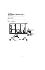
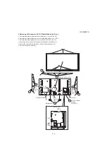
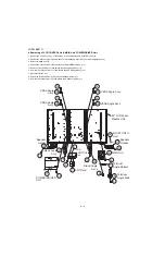
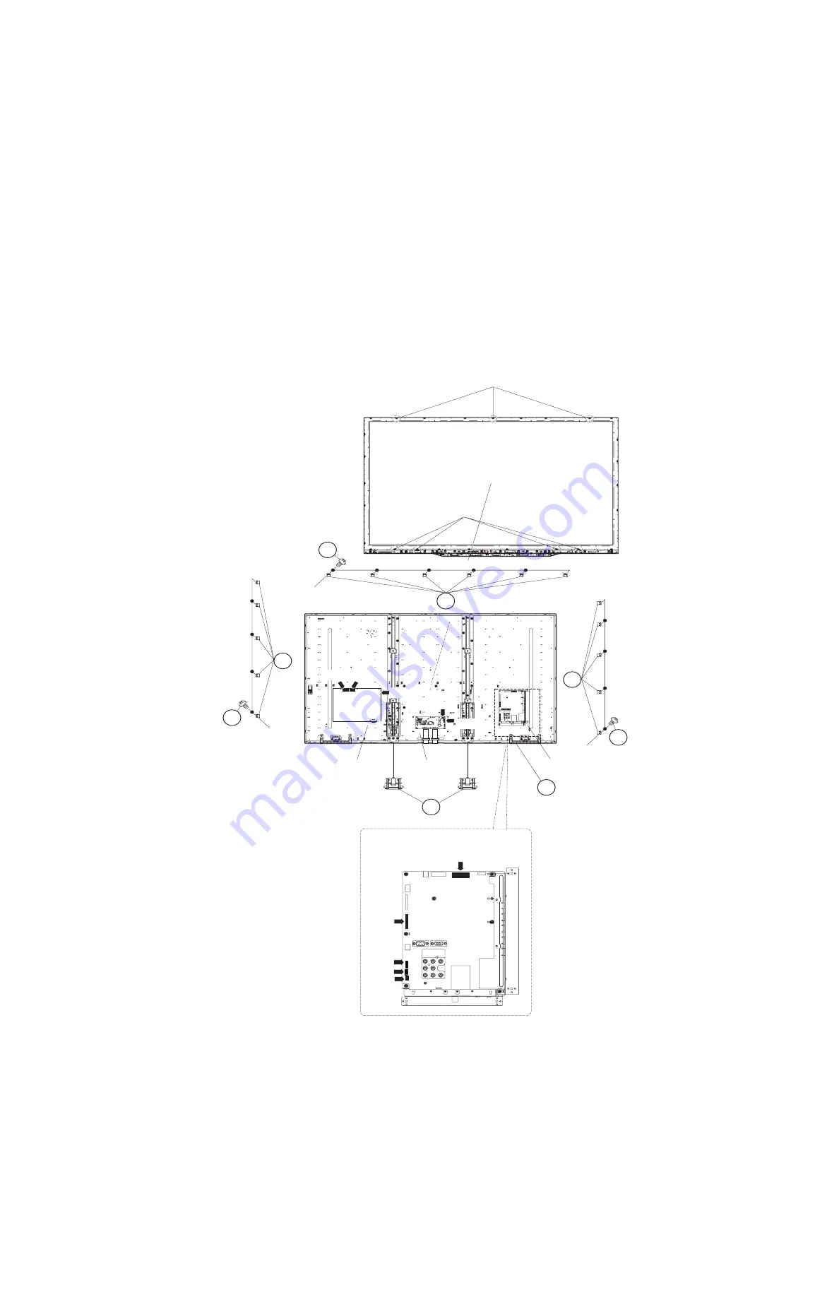
3. Removing of Connectors, 90” LCD Panel Module Unit Ass’y.
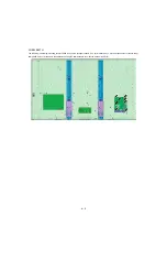
1. Disconnect the following connectors from the MAIN Unit. ( LV, PD,IR, BT, UB)
2. Disconnect the following connectors from the POWER/DRIVER Unit. (L1, L2, PD)
3. Disconnect the following connectors from the LCD CONTROL Unit. (PL, LV)
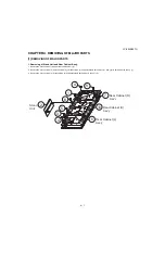
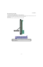
4. Remove the 16 lock screws (1) and detach the 16 Module Fix Angle Ass'y (2).
5. Remove the 7 Hooks and detach the 90" LCD Panel Module Unit Ass'y (3).
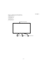
6. Remove the 2 Bottom Covers (4).
1
2
2
1
1
2
Module
Fix
Angle
Ass'y
Module
Fix
Angle
Ass'y
Module Fix Angle Ass'y
MAIN Unit
LCD
Control
Unit
POWER/DRIVER
Unit
Hook
Hook
[L1] [L2]
[PD]
[PD]
[PL]
[LV]
3 90" LCD Panel
Module
Unit Ass'y
MAIN Unit
4
Bottom cover
[UB]
[IR]
[BT]
[LV]
[PD]
Summary of Contents for LC-90LE657U
Page 6: ...LC 90LE657U 1 1 LC 90LE657U Service Manual CHAPTER 1 SPECIFICATIONS 1 SPECIFICATIONS ...
Page 7: ...LC 90LE657U 2 1 LC 90LE657U Service Manual CHAPTER 2 OPERATION MANUAL 1 OPERATION MANUAL ...
Page 8: ...LC 90LE657U 2 2 ...
Page 9: ...LC 90LE657U 2 3 ...
Page 10: ...LC 90LE657U 3 1 LC 90LE657U Service Manual CHAPTER 3 DIMENSIONS 1 DIMENSIONS ...
Page 66: ...LC 90LE657U 7 3 MEMO ...
Page 75: ...LC 90LE657U ...
Page 106: ...LC 90LE657U 2 20 ...
Page 129: ...LC 90LE657U ...
Page 134: ...LC 90LE657U 1 2 MEMO ...

