LC-90LE657U
4 – 1
LC-90LE657U
Service Manual
CHAPTER 4.
REMOVING OF MAJOR PARTS
[1] REMOVING OF MAJOR PARTS
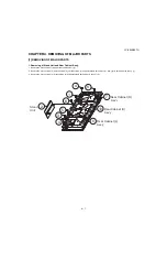
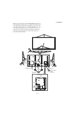
1. Removing of Stand Unit and Rear Cabinet Ass’y.
1. Remove the 4 lock screws (1) and detach the Stand Unit (2).
2. Remove the 3 lock screws (3), 20 lock screws (4), 10 lock screws (5) and detach the Rear Cabinet (L) Ass'y (6), Rear Cabinet (R) Ass'y (7).
3. Remove the 5 lock screws (8), 8 lock screws (9) and detach the Rear Cabinet (C) Ass'y (10).
4
3
4
5
1
2
Stand
Unit
6
Rear Cabinet (L)
Ass'y
7
Rear Cabinet (R)
Ass'y
10
Rear Cabinet (C)
Ass'y
9
8
Summary of Contents for LC-90LE657U
Page 6: ...LC 90LE657U 1 1 LC 90LE657U Service Manual CHAPTER 1 SPECIFICATIONS 1 SPECIFICATIONS ...
Page 7: ...LC 90LE657U 2 1 LC 90LE657U Service Manual CHAPTER 2 OPERATION MANUAL 1 OPERATION MANUAL ...
Page 8: ...LC 90LE657U 2 2 ...
Page 9: ...LC 90LE657U 2 3 ...
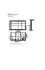
Page 10: ...LC 90LE657U 3 1 LC 90LE657U Service Manual CHAPTER 3 DIMENSIONS 1 DIMENSIONS ...
Page 66: ...LC 90LE657U 7 3 MEMO ...
Page 75: ...LC 90LE657U ...
Page 106: ...LC 90LE657U 2 20 ...
Page 129: ...LC 90LE657U ...
Page 134: ...LC 90LE657U 1 2 MEMO ...

