16
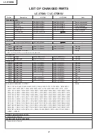
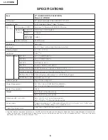
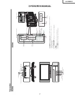
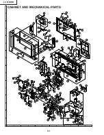
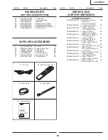
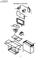
LC-37DB5U
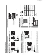
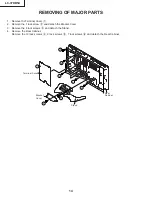
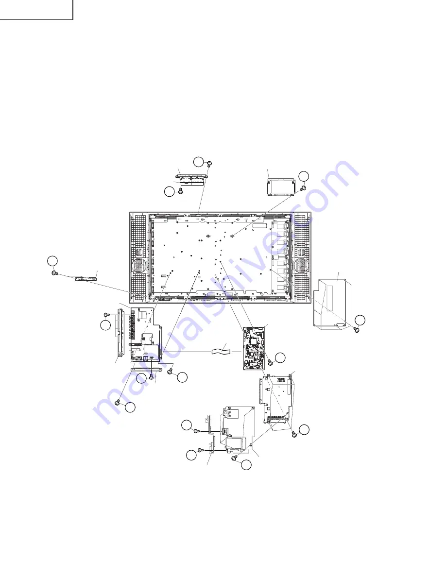
10. Remove the 4 lock screws
w
and FFC. Detach the Main Shield B and Digital PWB.
11. Remove the 4 lock screws
e
and detach the Digital PWB.
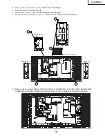
12. Remove the 2 lock screws
r
and detach the Jack Cover C.
13. Remove the 2 lock screws
t
and detach the Main PWB.
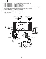
14. Remove the 3 lock screws
y
and the 1 lock screw
u
, and detach the AV PWB. Remove 1 lock screw
i
and
detach the Jack Cover B. Remove the 4 lock screws
o
and detach the Jack Cover A.
15. Remove the 6 lock screws
p
and detach the Power PWB.
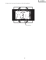
16. Remove the 4 lock screws
a
and detach the LCD Control PWB.
17. Remove the 2 lock screws
s
and detach the R/C, LED PWB.
18. Remove the KEY PWB.
18-1. Remove the 2 lock screws
d
from the Top Control Cover.
18-2. Remove the 3 lock screws
f
from the KEY PWB.
24
23
21
20
15
22
R/C, LED PWB
Main PWB
Main Shield B
POWER PWB
LCD Control PWB
AV PWB
FFC
Jack Cover A
Jack Cover C
Jack Cover B
12
13
16
17
18
19
KEY PWB
Top Control Cover
Digital PWB
14
14


