background image

25

HT-CN300W_A_4.fm

02/7/11

HT-CN300W

B

asic Ope

ration

- Enjo

y Sur

ro

und Soun

(s

o

und mode) -

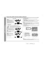
Enjoy Surround Sound (sound mode) (continued)

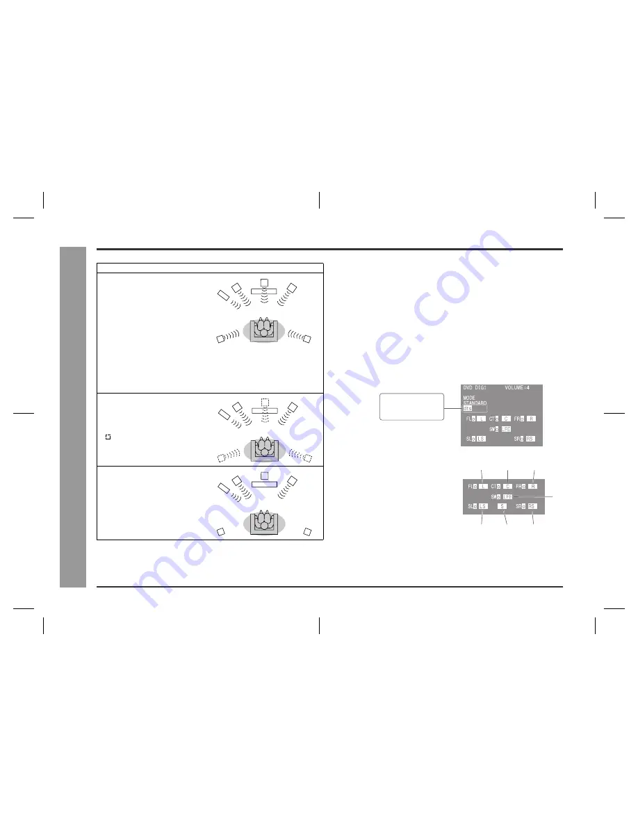
Dolby Digital and DTS:

The input signal is recognised automatically and the unit's indicator appears.

Dolby Pro Logic II:

z

The indicator appears on the display of the main unit when the 2ch signals are
entered to extend them to the 5.1ch surround sound.

z

Even the 2ch sound recorded with Dolby Digital will be extended to the 5.1ch.

Notes:

z

When the surround mode is set to "STANDARD", the sound of monaural signals is
heard only from the centre speaker.

z

When the surround mode is set to "VIRTUAL", the same monaural sound is
reproduced in both the front right and front left channels.

TV screen display:

The surround types are displayed also on the TV screen only when the unit is set to
DVD or VIDEO (see page 23).


Note:

The settings appear only when the TV is connected with a video cable. They will not
appear when the TV is connected with an S-video cable.

Acoustic effect

Standard

The maximum of 5.1ch surround sound 
is reproduced to provide three-
dimensional effect. This unit 
automatically emits the 5.1ch sound 
according to the recorded audio signal.

"STANDARD" appears on the display 
of the unit and TV screen.

Dynamic sound

You can enjoy normal surround sound with various scenes.

MOVIE:

The bass level is increased for powerful sound effect.

MUSIC:

You can enjoy lively sound by producing the articulate sound.

NIGHT:

Soft but powerful sound is achieved even at low volumes.

Virtual

Although no sound is heard from the 
surround speakers, you can still enjoy 
2.1ch surround sound as if they exist.

It sounds as if speakers are also placed 
in .

"VIRTUAL" appears on the display of 
the unit and TV screen.

Stereo

You can enjoy the great acoustic 
effects of the front speakers and 
subwoofer.

"STEREO" appears on the display of 
the unit and TV screen.


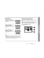
1

Front Left Signal Indicator

2

Centre Signal Indicator

3

Front Right Signal Indicator

4

Surround Left Signal Indicator

5

Surround Monaural Signal 
Indicator

6

Surround Right Signal Indicator

7

Low Frequency Effect Signal 
Indicator

DOLBY DIGITAL
DOLBY PROLOGIC II
dts

1

2

3

4

5

6

7

Summary of Contents for HT-CN300W

Page 1: ... product To obtain the best performance from this product please read this manual carefully It will guide you in operating your SHARP product HT CN300W Home Cinema Command consisting of HT CN300W main unit CP CN300WF front speakers CP CN300WC centre speaker and CP CN300WR surround speakers ...

Page 2: ...s appliance to dripping or splashing No objects filled with liquids such as vases should be placed on the apparatus Notes z The letters in brackets contained in the model number indicate the colour of the product only Operation and specifications are unaffected Contents Page General Information Accessories 2 Precautions 3 Controls and indicators 4 6 Connections Speaker connections 7 8 Aerial conne...

Page 3: ...trol 1 AC adaptor for remote control 1 AA size battery UM SUM 3 R6 HP 7 or similar 2 Labels for remote control 1 FM AM loop aerial 1 Remote control sensor 1 Double sided tape for remote control sensor 1 Video cable 1 Speaker cushion 20 Speaker connection lead 5 RADPA6006BGZZ Green Surround left 15 m 45 Front left 5 m 15 Red White Blue Grey Centre 5 m 15 Front right 5 m 15 Surround right 15 m 45 ...

Page 4: ...gher voltage other than that which is specified is dangerous and may result in a fire or other type of accident causing damage SHARP will not be held responsible for any damage resulting from use of this unit with a voltage other than that which is specified Volume control The sound level at a given volume setting depends on speaker efficiency location and various other factors It is advisable to ...

Page 5: ... Volume Up and Down Buttons 23 11 DVD Button 18 12 Video 1 Button 18 13 Tuner Band Button 27 14 Video 2 Auxiliary Button 18 15 Memory 1 2 Buttons for Other Equipment 19 16 Label Sealing Area 21 17 Clock Button 22 18 Memory Button 28 19 Timer Sleep Button 32 20 TV Screen Display Button 23 21 Dimmer Button 23 22 Extra Bass Demo Mode Button 13 23 23 Equaliser Mode Selector Button 23 24 Cursor Button ...

Page 6: ...tor 13 12 On Stand by Button 13 13 Remote Control Sensor Socket 8 14 TV Type Switch 11 15 TV Monitor Output Sockets 10 16 DVD Video Input Sockets 10 17 Video and Audio Input Sockets VIDEO 2 11 18 Video and Audio Input Sockets VIDEO 1 11 19 AC Voltage Selector 12 20 Subwoofer 21 AC Power Lead 12 22 DVD Optical Digital Audio Input Socket 10 23 DVD Coaxial Digital Audio Input Socket 10 24 Span Select...

Page 7: ...ou place the remote control sensor as the adhesive tape may damage or peel the surface coating when the tape is removed z Never locate the remote control sensor in an unstable place Otherwise it may fall Note Fix the remote control sensor on a flat surface 1 1 3 2 2 5 Bottom Front Side 6 4 3 Front Speaker right Red Front Speaker left White Centre Speaker Green Surround Speaker right Grey Surround ...

Page 8: ... connections Speaker connections Front speaker right Front speaker left Surround speaker right Main unit with subwoofer Surround speaker left Centre speaker Grey Black Red Red Black White Red Red Black Grey Red Black Blue Red Black Red Blue White Green Green ...

Page 9: ...attach it to a stand or on a wall with screws not supplied Notes z Placing the aerial on the unit or near the AC power lead or the remote sensor may cause noise pickup Place the aerial away from the unit for better reception z Do not connect the attached FM aerial to an external FM aerial Otherwise trouble may occur Installing the AM loop aerial Remotecontrolsensorconnection Caution z Hold the con...

Page 10: ... TV Camcorder Satellite receiver etc VCR S video cable See page 10 See page 11 See page 11 Video cable Audio cable Video cable supplied DVD player Optical digital audio cable or Coaxial digital audio cable S video cable Video cable Tape deck etc Audio cable See page 10 See page 11 Only one video cable is supplied with this unit Video cable Audio cable Video cable Audio cable Video cable Audio cabl...

Page 11: ...le or the coaxial digital cable To connect to the video socket with the video cable Note When connecting a DVD player with a video cable be sure to use another video cable for the TV To connect to the S video socket with the S video cable Note When connecting a DVD player with an S video cable be sure to use another S video cable for the TV This unit cannot convert the S video signal into the vide...

Page 12: ...OUT sockets when the equipment is connected to the DVD or VIDEO 1 IN sockets If connected to the VIDEO 2 IN sockets they are emitted from the VIDEO 1 OUT sockets If connected to the AUX IN sockets or whilst in the tuner mode only the sound is emitted Video cable Video cable Audio cable Audio cable To audio output sockets To video output socket VCR To audio input sockets To video input socket To au...

Page 13: ...ctor to the appropriate voltage number using a screwdriver 110 V 127 V or 220 V 240 V Notes z You can operate the remote control with batteries in areas where the AC adaptor lead cannot reach see page 16 z Remove the AC adaptor from the AC socket if the unit will not be in use for a prolonged period of time z Use only the supplied AC adaptor Another adaptor may cause an electric shock or fire z If...

Page 14: ...oll To cancel the demonstration mode When the unit is in the power stand by mode demonstration mode press the X BASS button The demonstration mode will be cancelled and the display will disappear To return to the demonstration mode When the unit is in the power stand by mode press the X BASS button again Note When the power is on the X BASS button can be used to select the extra bass mode see page...

Page 15: ...ust above the height of your ears The supplied speakers may be placed beside or near the TV as they are magnetically shielded However colour variation may occur depending on the type of the TV If colour variation occurs Turn off the TV from the power switch After 15 30 minutes turn the TV on again If the colour variation is still present Move the speakers further away from the TV Refer to the user...

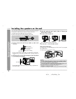
Page 16: ...y inserting the screw head into the slot on the back of the speaker Set the speaker lead in the recess preventing it from being caught between the wall and the speaker 9 mm 3 8 5 mm 3 16 3 2 mm 1 8 Min 22 mm 7 8 3 5 mm 9 64 Min 18 5 mm 23 32 Wall mounting screw not supplied Wall surface Recess Wall surface 3 Raise the speaker the most upward Refer to Changing the speaker angle for details 4 Drive ...

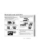
Page 17: ...th a soft cloth z Keep the remote control away from moisture heat shock and vibrations Test of the remote control Point the remote control directly at the remote sensor The remote control can be used within the range shown below z Press the ON STAND BY button Does the power turn on Now you can enjoy your system z When the signal is received the remote control indicator will flash Whilst in the dim...

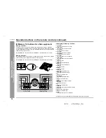
Page 18: ... VOLUME Decreases the volume 4 VOLUME Increases the volume 5 STANDARD Sets the sound mode to STANDARD 6 DYNAMIC SOUND Switches the dynamic sound 7 SET UP Changes the speaker setting 8 CLEAR Deletes the tuner pre selections 9 CLOCK Sets or displays the clock time 10 MEMORY Presets the tuner 11 TIMER SLEEP Sets the power to ON or STAND BY at the desired time 12 DIMMER Adjusts the brightness of the m...

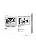
Page 19: ...en the unit is set to DVD Switch the setting according to the connected sound source by pressing it repeatedly 2 TUNER BAND Selects the tuner function or switches the frequency band 3 VIDEO 2 AUX Selects the VIDEO 2 or AUX mode 4 VIDEO 1 Selects the VIDEO 1 mode 1 2 3 4 Optical Coaxial 1 DVD ON STAND BY Sets the DVD power to ON or STAND BY 2 TV ON STAND BY Sets the TV power to ON or STAND BY 3 Ski...

Page 20: ...Memory 2 buttons Initial setting for Memory 1 buttons For details refer to the operation manual attached to the other equipment OPEN 1 2 3 4 13 14 15 16 5 6 7 8 9 19 20 21 10 11 12 22 23 24 18 17 1 TV VCR Switches the input to TV or VCR 2 VCR CH Switches up the VCR channels 3 TV VOL Turns up the TV volume 4 TV CH Switches up the TV channels 5 TV VOL Turns down the TV volume 6 TV CH Switches down t...

Page 21: ...tor switch to MEMORY 2 2 Move the LEARN TRANSMIT selector switch to LEARN The red learn indicator will light up Though the red and green learn indicators light up alternately after approx 15 seconds you can go on to the next step 3 Press down the desired button on the remote control for 2 seconds or more The green learn indicator will flash the red indicator remains lit Lights up Alternately light...

Page 22: ... If initialisation is performed all the stored functions will be cleared 1 Move the LEARN TRANSMIT selector switch to LEARN 2 Press down the desired button on the remote control for 2 seconds or more 3 Perform steps 4 6 in Memorising operations in the Memory 2 buttons for other equipment see page 20 Registrable buttons 1 Move the LEARN TRANSMIT selector switch to LEARN The red learn indicator will...

Page 23: ...et when the unit is first installed or it has been reset see page 35 0 00 The 24 hour display will appear 0 00 23 59 AM 12 00 The 12 hour display will appear AM 12 00 PM 11 59 AM 0 00 The 12 hour display will appear AM 0 00 PM 11 59 4 Press the or button to adjust the hour and then press the ENTER button z Press the or button once to advance the time by 1 hour Hold it down to advance continuously ...

Page 24: ...VOLUME button for decreasing Bass control When the X BASS button is pressed the unit will enter the extra bass mode which emphasises the bass frequencies To cancel the extra bass mode press the X BASS button Equaliser When the EQ button is pressed the current mode setting will be displayed To change to a different mode press the EQ button repeatedly until the desired sound mode appears Note Bass c...

Page 25: ... theatre system Standard Dynamic sound The disc recorded in the Dolby Digital system is recognised by this unit automatically when it is played back Virtual Disc with this trademark Stereo DTS Digital Theater Systems One of the digital audio systems for theatrical use As the sound quality is emphasised you can enjoy the realistic sound effect in the home theatre system The disc recorded in the DTS...

Page 26: ...ideo cable Acoustic effect Standard The maximum of 5 1ch surround sound is reproduced to provide three dimensional effect This unit automatically emits the 5 1ch sound according to the recorded audio signal STANDARD appears on the display of the unit and TV screen Dynamic sound You can enjoy normal surround sound with various scenes MOVIE The bass level is increased for powerful sound effect MUSIC...

Page 27: ...tandard mode During playback press the STANDARD button STANDARD appears on the display of the unit and TV screen To enjoy in the virtual mode During playback press the 2CH button repeatedly to select VIRTUAL VIRTUAL appears on the display of the unit and TV screen To enjoy in the stereo mode During playback press the 2CH button repeatedly to select STEREO STEREO appears on the display of the unit ...

Page 28: ...reo broadcasts will not be played in stereo 1 Press the ON STAND BY button to turn the power on 2 Press the TUNER BAND button repeatedly to select the desired frequency band FM ST FM or AM 3 Press the or button to tune in to the desired station Manual tuning Press the or button as many times as required to tune in to the desired station Auto tuning When the or button is pressed for more than 0 5 s...

Page 29: ...et channel number z Store the stations in memory in order starting with preset channel 1 z When is displayed a station has already been stored in memory 4 Within 30 seconds press the MEMORY button to store that station in memory If the MEMORY and preset number indicators go out before the station is memorised repeat the operation from step 2 5 Repeat steps 1 4 to set other stations or to change a ...

Page 30: ...ed If the subwoofer is changed to SW NO whilst the front speakers are set to F SMALL they are changed to F LARGE When the front speakers are changed to F SMALL whilst the subwoofer is set to SW NO it is changed to SW YES 1 Press the SET UP button 2 Within 10 seconds press the or button to select SP SIZE and press the ENTER button 3 Within 10 seconds press the or button to select the desired speake...

Page 31: ...tance you set and provide the same effect as if they are placed at the same distance from the listening position 1 Press the SET UP button 2 Within 10 seconds press the or button to select SP DELAY and press the ENTER button 3 Within 30 seconds press the or button to select the desired speaker 4 Within 30 seconds press the or button to select the distance and press the ENTER button TV screen z You...

Page 32: ... 10 seconds press the or button to select SP LEVEL and press the ENTER button 3 Within 10 seconds press the or button to select the desired speaker 4 Within 10 seconds press the or button to adjust the level TV screen z You can adjust the level at 1 dB intervals z To adjust the levels of other speakers repeat the operation from step 3 z You can complete the setting operation by pressing the SET UP...

Page 33: ...er function 1 Press the ON STAND BY button to turn the power on 2 Press the TUNER BAND button Tune in to the desired station See page 27 3 Adjust the volume using the VOLUME or button Do not turn the volume up too high 4 Press the TIMER SLEEP button repeatedly until is displayed 5 Press the or button to specify the hour to start then press the ENTER button 6 Press the or button to specify the minu...

Page 34: ... select the other source in step 1 of Setting the sleep timer but this unit cannot set the sleep timer of other equipment To confirm the remaining sleep time Press the TIMER SLEEP button z The remaining sleep time is displayed for about 5 seconds z You can change the remaining sleep time whilst it is displayed by pressing the ENTER button steps 3 4 To cancel the sleep operation Press the ON STAND ...

Page 35: ...e same distance from the listener P 14 z Are speakers adjusted to the same level P 31 Noise is heard during playback z Move the unit away from any computers or mobile phones Symptom Possible cause Reference page Radio makes unusual noise consecutively z Move the unit away from any computers or mobile phones z Is the FM AM loop aerial placed properly Move the aerial away from the AC power lead if l...

Page 36: ...to the inside of the unit It may cause malfunctions Symptom Possible cause Reference page No images are displayed z Is TV turned on P 18 z Is the input of TV switched P 18 z Is TV connected properly P 10 Settings are not displayed on the TV screen z The settings will not appear when TV is connected with an S video cable Verify on the main unit display P 23 Interference or noise occurs on the TV im...

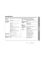
Page 37: ...0 W 30 W 10 T H D 1 kHz Subwoofer MPO 60 W 10 T H D 100 Hz RMS 30 W 10 T H D 100 Hz Type Subwoofer System Magnetic shield 160 mm 6 1 4 Woofer Maximum input power 60 W Rated input power 30 W Impedance 6 ohms Type Full Range Speaker System Magnetic shield 80 mm 3 1 8 Speaker Maximum input power 60 W Rated input power 30 W Impedance 6 ohms Dimensions Width 104 mm 4 1 8 Height 110 mm 4 3 8 Depth 123 m...

Page 38: ...MEMO ...

Page 39: ...MEMO ...

Page 40: ...TINSE0016BGZZ 02H Y HK 2 SHARP CORPORATION ...

Reviews: