


FO-77U
UX-66U
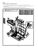
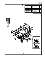
Fig. 8
3 – 10
Head frame and thermal head
8
Parts list (Fig. 8)
No.
Part name
Q’ty
No.
Part name
Q’ty
1
Platen gear
1
2
Platen bearing
2
3
Platen roller
1
4
Connector
1
5
Screw (3
×
6)
1
6
Head earth cable
1
7
Screw (3
×
6)
1
8
Head holder, left
1
9
Screw (3
×
6)
1
10
Head holder, right
1
11
Thermal head
1
12
Document sensor lever
1
13
Document sensor lever
1
spring
14
Head spring 2
2
15
Head spring 1
3
16
Head frame
1
12
12
13
13
14
14
14
15
15
15
11
11
16
16
2
2
2
1
1
3
3
4
4
5
6
7
7
8
8
9
9
6
5
10
10
Fix position of Document
Sensor lever spring
OK
NG
Summary of Contents for FO-77
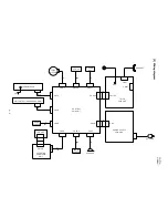
Page 65: ...FO 77U UX 66U Control PWB parts layout Top side 6 7 ...
Page 66: ...FO 77U UX 66U Control PWB parts layout Bottom side 6 8 ...
Page 69: ...FO 77U UX 66U TEL LIU PWB parts layout Top side 6 11 ...
Page 70: ...FO 77U UX 66U 6 12 TEL LIU PWB parts layout Bottom side ...
Page 72: ...FO 77U UX 66U Power supply PWB parts layout 6 14 RDENT2142XHZZ F2 ...
Page 97: ...FO 77U UX 66U 14 M E M O ...


