


FO-2970MU
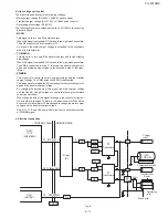
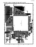
Fig. 24
H
L
HS DETECTOR
CML
CI DETECTOR
0:LINE
1:BZ
SPEAKER
LINE
+5VA
+24VA
DG
BZCONT
TELOUT
TEL IN
EXT.
RX
RXIN
TXOUT
CML
HS
0:CID
CONTROL PWB
LIU PWB
SIGTX
SIXGRX
1:RX
0:MID
1:HIGH
TEL MUTE
(H:MUTE)
IC15 G.A
LR38784A
SP MUTE
(H:MUTE)
BZOUT
BZCONT
RCVOL
VOL C
VOL B
VOL A
SP MUTE
TEL MUTE
CI
RHS
GAIN-C
CML
HS
IC5 SH2
(7041)
HOOK-SW PWB
TX
GAIN -C
CI
MIC MUTE
IC8
MODEM(FM336)
SPKR
(Example: Fax signal send)
5 – 23
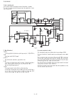
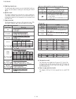
[4] Circuit description of power supply
PWB
1. Noise filter circuit
The filter part removes noises generated from the power unit to avoid
noise release outside and prevent external noises from entering.
Excessive surge such as thunder is prevented by varistor Z1.
2. Rectified smoothing circuit
The rectified smoothing circuit rectifies AC input at diodes D10, 11, 12,
and 13, and then smoothens it at capacitor C5 to supply DC voltage to
the switching part.
3. Switching part
This circuit adopts the ringing choke converter system of self-excited
type.
By repeating ON/OFF of MOS FETQ1, this system converts DC voltage
supplied from the rectified smoothing part into high-frequency pulse,
stores energy in the primary winding of transformer T1 during ON pe-
riod, releases energy to the secondary winding during OFF period, and
supplies power.
Frequency changes according to output load; As load increases, ON
period becomes longer.
Constant voltage is controlled by applying feedback to the control circuit
via photo coupler from 24 V output.
The overcurrent protective circuit detects prolonged ON period caused
by excessive output load, lengthens Q1 OFF period by using the control
circuit, and restricts energy stored in the primary winding of transformer
T1.
Increase of the secondary output voltage 24 V is led to the overcurrent
condition by turning on power zener diode D202 between 24 V output
and GND.
Thus overvoltage is protected by operating the overcurrent protective
circuit of the control circuit.
4. 24 V circuit
To supply output, transformer T1 output is rectified and smoothened
with the use of diode D101 and capacitor C101. Voltage is controlled by
Volume VR101.
5. +5 V circuit
Transformer T1 output is rectified and smoothened with the use of diode
D301 and capacitor C301 to sta5 V output by using 3-terminal
regulator IC301.
6. Heater circuit
To maintain the optimal temperature, the heater lamp is controlled by
HLON signal from the control panel.
This HLON signal is to switch ON/OFF the heater lamp. If this signal is
input LOW, PC2 is switched ON, resulting TRIACK TRA1 ON.
Accordingly, AC power is supplied to the heater lamp to switch the heater
lamp ON.
7. Zero cross circuit
When AC input reaches the zero cross point (0 V), PC3 is switched ON.
When Q501 is switched ON, the zero cross signal is output to the con-
trol panel.
Summary of Contents for FO-2970M
Page 70: ...FO 2970MU 6 10 Control PWB parts layout Top side ...
Page 71: ...FO 2970MU Control PWB parts layout Bottom side 6 11 ...
Page 73: ...FO 2970MU 6 13 TEL LIU and Hook SW PWB parts layout Top side ...
Page 74: ...FO 2970MU 6 14 TEL LIU and Hook SW PWB parts layout Bottom side ...


