


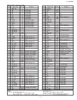


FO-2970MU
NC = Not connect
RESERVED = No external connection allowed
Interface description: HOST = Modem control unit (Host)
DTE = Data terminal equipment
PIN
Signal Name
I/O Type
Interface
3
51
RESERVED
–
–
52
VSUB
GND
–
53
VSS
GND
–
54
NC
–
NC
55
NC
–
NC
56
SLEEP
MI
Modem interconnect
57
VDD1
PWR
–
58
RESERVED
–
–
59
RESERVED
–
–
60
NC
–
NC
61
SR1IO
MI
Modem interconnect
62
VCORE
PWR
–
63
VDD1
PWR
–
64
XTCLK
IA
DTE Serial interface
65
VSS
GND
–
66
RESERVED
–
–
67
RXD
OA
DTE Serial interface
68
/DTR
IA
DTE Serial interface
69
VDD1
PWR
–
70
IA_SLEEP
MI
Modem interconnect
71
VGG
PWR
–
72
YCLK
OA
Overhead signal
73
XCLK
OA
Overhead signal
74
EYEXY
OA
Diagnosis signal
75
/DSR
OA
DTE Serial interface
76
/RI
OA
Telephone lines interface
77
RINGD
IA
Telephone lines interface
78
/RTS
IA
DTE Serial interface
79
IRQ
OA
Host interface
80
VSS
GND
–
81
GPO0
MI
Modem interconnect
82
RESERVED
–
–
83
RESERVED
–
–
84
VDD1
PWR
–
85
XTALI/CLKIN
I
Overhead signal
86
XTALO
O
Overhead signal
87
D0
IA/OB
Host interface
88
D1
IA/OB
Host interface
89
D2
IA/OB
Host interface
90
D3
IA/OB
Host interface
91
D4
IA/OB
Host interface
92
VDD1
PWR
–
93
D5
IA/OB
Host interface
94
D6
IA/OB
Host interface
95
D7
IA/OB
Host interface
96
RS0
IA/OB
Host interface
97
RS1
IA/OB
Host interface
98
PLL VDD
PWR
–
99
VSS
GND
–
100
PLL GND
GND
–
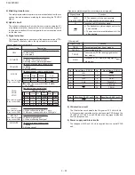
PIN
Signal Name
I/O Type
Interface
3
1
RESERVED
–
–
2
RS2
IA
Host interface
3
RS3
IA
Host interface
4
RS4
IA
Host interface
5
/CS
IA
Host interface
6
/WR
IA
Host interface
7
/RD
IA
Host interface
8
/RDCLK
OA
DTE Serial interface
9
/RLSD
OA
DTE Serial interface
10
TDCLK
OA
DTE Serial interface
11
TXD
IA
DTE Serial interface
12
/CTS
OA
DTE Serial interface
13
VDD1
PWR
–
14
RESERVED
–
–
15
RESERVED
–
–
16
VSS
GND
–
17
NC
–
NC
18
/RESET
OA
Modem interconnect
19
SR4OUT
OA
Modem interconnect
20
NC
–
NC
21
SR4IN
IA
Modem interconnect
22
CLK_OUT
OA
Modem interconnect
23
EYESYNC
OA
Diagnosis signal
24
EYECLK
OA
Diagnosis signal
25
MAVSS
GND
–
26
MAVDD
PWR
–
27
SPKR
O(DF)
Telephone lines interface
28
TXA2
O(DD)
Telephone lines interface
29
TXA1
O(DD)
Telephone lines interface
30
VREF
MI
Modem interconnect
31
VC
MI
Modem interconnect
32
RIN
I(DA)
Telepone lines interface
33
MAVSS
AGND
–
34
/POR
LA
Modem interconnect
35
RESERVED
–
–
36
RESERVED
–
–
37
/TALK
O(DD)
Telephone lines interface
38
VDD
PWR
–
39
RESERVED
–
–
40
RESERVED
–
–
41
NC
–
NC
42
M_CNTRL_SIN
IA
Modem interconnect
43
M_CLKIN
IA
Modem interconnect
44
M_TXSIN
IA
Modem interconnect
45
M_SCK
IA
Modem interconnect
46
M_RXOUT
IA
Modem interconnect
47
M_STROBE
IA
Modem interconnect
48
RESERVED
–
–
49
OH
O(DD)
Telephone lines interface
50
VDD
PWR
–
5 – 19
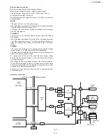
FM336 (IC8) Terminal description
Notes:
I/O types: MI = Modem interconnect
IA, IB = Digital input
OA, OB = Digital output
I(DA) = Analog input
O(DD), O(DF) = Analog output
Summary of Contents for FO-2970M
Page 70: ...FO 2970MU 6 10 Control PWB parts layout Top side ...
Page 71: ...FO 2970MU Control PWB parts layout Bottom side 6 11 ...
Page 73: ...FO 2970MU 6 13 TEL LIU and Hook SW PWB parts layout Top side ...
Page 74: ...FO 2970MU 6 14 TEL LIU and Hook SW PWB parts layout Bottom side ...


