DV-L70S
DV-L70BL
DV-L70W
46
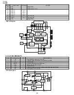
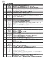
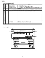
Pin No.
I/O
Terminal name
Operation function
Remarks
2
O
BLK
Blanking signal output
H ... OSD display
3
L ... Blank (television image)
5
I
HSYNC
Horizontal synch signal input
Negative polarity input
6
I
VSYNC
Vertical sync signal inputNegative polarity input
7
I
SCLK
Serial clock input/output
Clock input during serial communication
with DVD microcomputer
8
O
SOUT
Serial data output
Data output during serial communication
with DVD microcomputer
9
I
SIN
Serial data input
Data input during serial communication
with DVD microcomputer
10
I
SYNC
Composite sync signal input
Used for sync judgment in the search mode.
11
I
PLLD
TVPLL lock signal input*
Used to judge whether TVPLL is locked in
the receiving frequency or not.
H ... Unlocked state
L ... Locked state
12
O
PLCS
TVPLL load EN output*
H ... During data transmission to TVPLL
L ... When data is not transmitted.
13
O
PCLK
Clock output for inner communication
Serial clock output to E
2
PROM/TVPLL*/DAC
14
O
POUT
Data output for inner communication
Serial data output to E
2
PROM/TVPLL*/DAC
15
I
SAFE
Fixed at “H”.
16
O
RGB
Fixed at “L”.
17
O
MRDY
READY output
READY signal output during serial
communication with DVD
H ... Command reception disable (BUSY state)
L ... Command reception enable (READY state)
18
O
POW
Power on/off control
DC/DC power control
H ... Power ON
L ... Power OFF (stand-by)
19
I
PIN
Data output for inner communication
Serial data input to E
2
PROM
20
O
K3
Not used.
22
O
K2
Key matrix output2
23
25
O
K1
Key matrix output1
26
O
K0
Key matrix output0
27
I
S3
Key matrix input3
Key matrix input
28
I
S2
Key matrix input2
29
I
S1
Key matrix input1
30
I
S0
Key matrix input0
31
I
ST/MT
Input for US setting
H ... US, L ... Japan
34
O
MONO
Not used.
36
O
S
AD input for battery monitor
39
O
M
Power button input
H ... Po wer ON
L ... Power OFF
35
I
AFT
AFT voltage input*
Tuner AFT voltage input
37
I
AGC
AGC voltage input*
Tuner AGC voltage input
38
I
VOL
Sound volume AD input
Sound VOL input
40
I
R/C
Remote control input
Infrared remote control input
42
O
MODW
Panel selection input(1)
43
44
MODN
Panel selection input(2)
45
O
VSW
Not used.
46
O
MIRST
DVD microcomputer reset output
H ... Normal, L ... Reset
47
O
DVD P
DVD circuit power control
H ... ON, L ... OFF
48
O
LCDSW
Liquid crystal panel open/close interrupt
H ... OPEN, L ... CLOSE
49
O
LCDH
Liquid crystal system circuit power control
H ... ON, L ... OFF
MODW
MODN
Display mode
H
H
Full-screen mode
H
L
Wide mode
L
H
Normal mode
L
L
Cinema mode
Summary of Contents for DV-L70BL
Page 2: ...DV L70S DV L70BL DV L70W 2 1 IMPORTANT SAFEGUARDS AND PRECAUTIONS ...
Page 6: ...DV L70S DV L70BL DV L70W 6 For details on the use of each control 4 PART NAMES ...
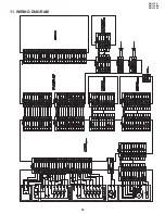
Page 53: ...53 DV L70S DV L70BL DV L70W 11 WIRING DIAGRAM ...
Page 82: ...Ref No Part No Description Code Ref No Part No Description Code 95 DV L70S DV L70BL DV L70W ...


