33
DV-L70S
DV-L70BL
DV-L70W
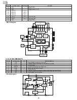
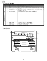
9-11. IC701 AN8473NS-1
Pin No.
Terminal name
Operation function
Pin No. Terminal name
Operation function
1
VH
Hole bias terminal
17
VM21
Motor power terminal 2
2
H3L
Hole element 3 negative input terminal
18
VM22
Motor power terminal 2
3
H3H
Hole element 3 positive input terminal
19
CS
Current detection terminal
4
H2L
Hole element 2 negative input terminal
20
NC
N. C.
5
H2H
Hole element 2 positive input terminal
21
A31
Drive output 3
6
H1L
Hole element 1 negative input terminal
22
A32
Drive output 3
7
H1H
Hole element 1 positive input terminal
23
PG2
Power current detection terminal 2
8
EC
Torque command input terminal
24
A21
Drive output 2
9
ECR
Torque command reference input terminal
25
A22
Drive output 2
10
FG
FG signal output terminal
26
PG1
Power current detection terminal 1
11
START
Start/stop selection terminal
27
A11
Drive output 1
12
VPUMP
Booster terminal
28
A12
Drive output 1
13
BC1
Booster capacitor connection terminal
29
NC
N. C.
14
BC2
Booster capacitor connection terminal
30
PWMSW
PWM frequency selection terminal
15
GND
GND terminal
31
VM12
Motor power terminal 1
16
VDD
Power terminal
32
VM11
Motor power terminal 1
11
10
8
9
30
0.1
µ
F
0.1
µ
F
100
µ
F
VPUMP
BC1
BC2
VDD
START
2200pF
Booster circuit
Thermal
protection
Output
circuit
OSC
Start/stop
FG
VH
H1H
H1H
H2H
H2L
H3H
H3L
100
Ω
100
Ω
EC
ECR
PWMSW
HIGH:40kHZ
LOW:80kHZ
SSET
VT
Vc1
FF
SRESET
PWMOUTL
PWMOUTU
5V
VM21
VM22
VM11
VM12
A11
A12
A21
A22
A31
A32
PG2
PG1
CS
X5
GND
Rcs=0.33
Ω
Amplification
Amplification
Hole
amplifier
matrix
Hole
bias
Absolute
value
(After checking the tolerance
of the electrical characteristics,
the customer determines the
resistance value.)
Spindle speed
control signal
PWM frequency
connection circuit
14
13
12
16
7
6
5
4
3
2
1
15
23
26
27
28
24
25
21
22
17
18
32
31
19
Distribution
circuit
• Block Diagram
Summary of Contents for DV-L70BL
Page 2: ...DV L70S DV L70BL DV L70W 2 1 IMPORTANT SAFEGUARDS AND PRECAUTIONS ...
Page 6: ...DV L70S DV L70BL DV L70W 6 For details on the use of each control 4 PART NAMES ...
Page 53: ...53 DV L70S DV L70BL DV L70W 11 WIRING DIAGRAM ...
Page 82: ...Ref No Part No Description Code Ref No Part No Description Code 95 DV L70S DV L70BL DV L70W ...


